Hi Mickey,
Thanks for following up with the helpful summary.
Yes, geometrical imperfections will/should have very little effect on an Eigenvalue Buckling Analysis. This is because an eigenvalue buckling analysis is an inherently first-order, linearly elastic analysis.
A detailed explanation is outside the scope of this post, but a really good introduction to this topic can be found in this relatively simple paper for practicing bridge engineers.
Simply put, to study the effect of imperfections (if any) you will have to conduct a geometrically nonlinear, or large displacement analysis. The above paper will go into much better detail than I ever could on this. This is also a good paper/text by the same author
(A leading UK Bridge Engineer). Again, this is a very good read which will help you understand the differences
That still doesn't quite answer the question on why you're getting very different load factors. Maybe its worth making another copy of your original model and defining the imperfection to be doubly sure. I've also made some comments on your model description:
1. OK,
2. I think strictly speaking you should be using shell elements (plate elements are typically for 2D applications like slabs). I'm unfamiliar with your software though.
3. By this, do you mean you have assigned translational restraints in all principal axes, to the lines representing the bottom and top flanges at the ends? Although its not a "real" application, and for testing purposes, be careful with how you idealise your supports. Knowledge of "what" the problem is obviously matters a bunch, but are you sure you want the edges of the beams to be torsionally restrained - I suppose without any bracing or a another beam to give it some warping resistance its a mechanism otherwise i.e. there is no torsional restraint.
4. Ok.
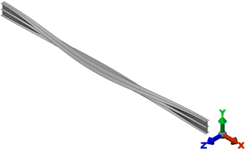
5. Yes, now I know a bit about the problem LTB will obviously govern here.
6. Fine, although I might try and further simplify the problem as a unit UDL applied to the TF where it meets the web panels.
7. Ok.
9. There are formulae available for simple cases in your local building code or textbook. You will need to calculate Mcr, the elastic critical buckling moment. This is the theoretical bending moment at which the beam will theoretically buckling (not accounting for imperfections). This is a helpful guide;
For bench-marking purposes and to make your validation as simple as possible, ensure that your model is a doubly-symmetric I-beam (i.e. bbf=btf and ttf = tbf) - the formulae are much simpler to use. To get the Mcr from your model, work out the BM in the beam in a static analysis (i.e. wl^2/8) and multiple it by the buckling load factor. Then simply compare etc.
Once you've gone through all that and you're still having trouble, feel free to shout. gl!