Continue to Site

Eng-Tips is the largest engineering community on the Internet

Intelligent Work Forums for Engineering Professionals

  • Congratulations cowski on being selected by the Eng-Tips community for having the most helpful posts in the forums last week. Way to Go!

Buckling of column in SAP2000 3

Status
Not open for further replies.

dccd

Civil/Environmental
Feb 19, 2021
150
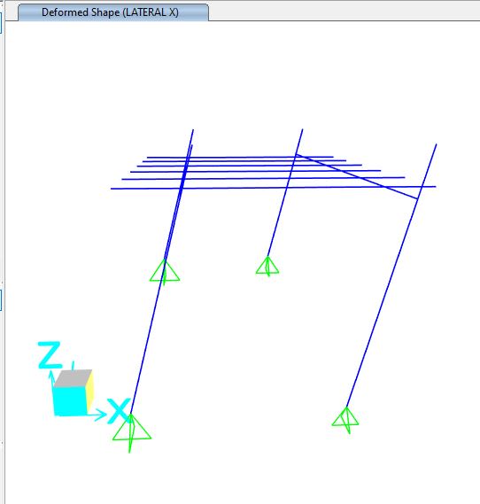
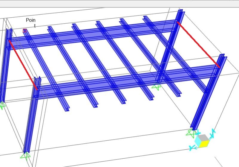
Hi , all. This is a steel frame made up of I-beam on top and I-beam column.

The I-beam on top is connected thru moment connection to the I-beam column below to restrain the major axis bending.

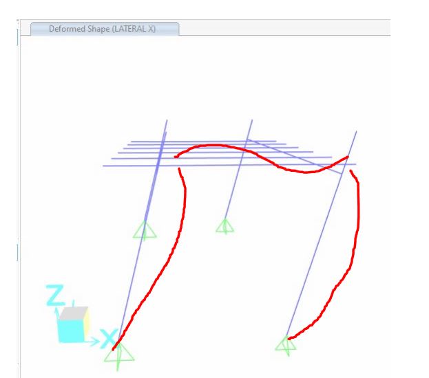
I understand that in major axis bedning of column (x axis)
frame_3_yngpbh.jpg
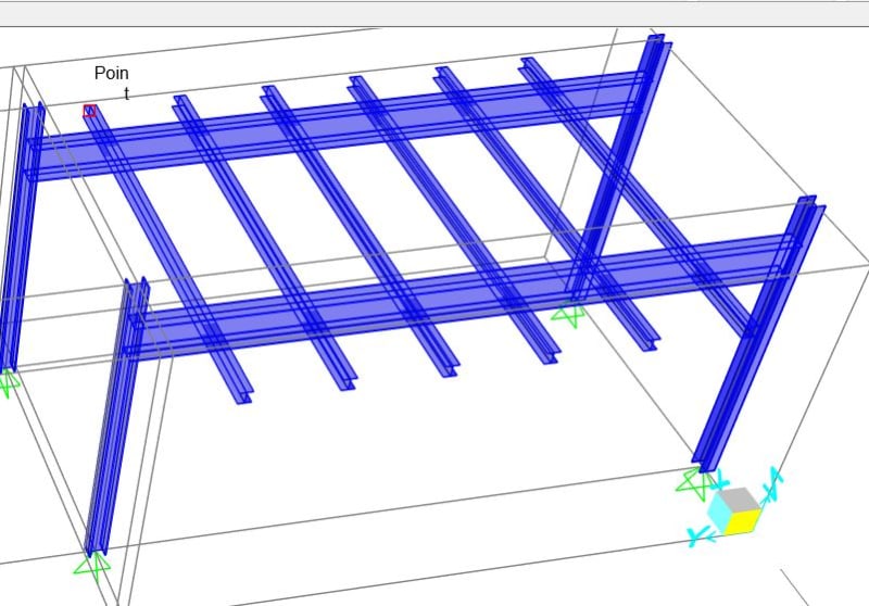
, it's pinned (bottom) , fixed (top) connection, so that k factor for buckling = 0.7 .

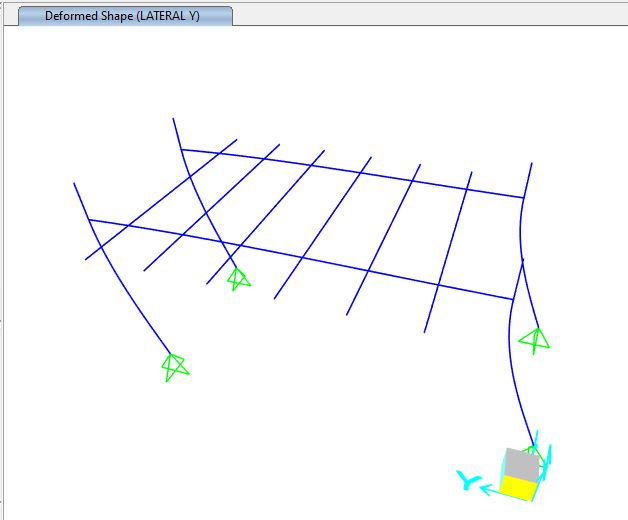
However, for minor axis bending ( y axis) , it's pinned free. In free condition, the frame shall be unstable, right ? But it seems that the SAP2000 still somehow detect it as pinned-pinned condition.

I have checked the buckling capacity of column, it's rather similar to the results that the SAP2000 gave. What's wrong with the model, can anyone help ?
 
Replies continue below

Recommended for you

@kostast88, releasing all moment on secondary clearly doesnt work. It made things worse, as you can see in the photos earlier, secondary joist is cantilever at both ends and simply supported in betweens


Will you post the deformed shape with nominal horizontal tip loads? and model showing the support conditions , joint releases with the set up that Mr. steveh49 proposed?..

I am familiar with old versions if the model is correct , the program should terminate with giving fatal error message. If the stability is provided by program , ( for some modelling with FEM and Push -over is valid) , the output will not be reliable...

With your modelling, ( the columns pin supported in X and Y direction, the joists supported to main beams with fictious column elements having length half of the heights of main beam + joist and pin connected to one of the beams either joist or beam ) the frame is unstable in X direction.. There is no way..

Regarding the frames with pin supported , the stability is provided with fixity of beam -column connection and there is no way that the buckling length can be less than 2* L .. And 2xL is valid for infinite rigid of the beam..


I will suggest you to look tutorials for the modelling issues..
 
@HTURKAK , I have posted the deformed shape under lateral load in x and y direction earlier, please refer to the attached image for your reference again .

LATERAL_X_ccyvrx.jpg


LATERAL_Y_y3ohbl.jpg
 
Remove the cantilever bit from your model and substitute them with a load representing the weight. Leave only the simply supported joists.
 
For the secondary member, I have removed the cantilever part and released the moment at the simply supported part, the program detect the system as unstable. (This is what I expected in real situtaion, the whoel strcuture isn't stable because it's pinned free condition in minor axis...) But the column still pass in the analysis. Surprisingly, the column doesnt fail due to minor axis buckling...


Why would release moment of the secondary member can render the whole structure unstable ?? ( When the secondary beam not released, the program detect it as restraint of the column against minor axis buckling) ??


The secondary member doesnt connect directly to thw column, how can the program detect it as restraint for minor axis buckling ??
 
Your first photo shows that 2 columns are rotated 90 degrees.Is that right? Or did you rotate them to get different buckling resistances on the 2 grids?

Therefore you effectively have a 3D structure. The pinned joists still provide some restraint to the beam which is rigidly connected to the columns (and they should). Since your model is 3D, these are activated when forces act in the X and Y direction respectively.

Try rotate all columns accordingly and you may get a complete failure this time.

Finally, since it passes strength and fails in stability, it fails.
 
My questions are still the same.....


Why would release moment of the secondary member can render the whole structure unstable ?? ( When the secondary beam not released, the program detect it as restraint of the column against minor axis buckling) ??


The secondary member doesnt connect directly to thw column, how can the program detect it as restraint for minor axis buckling ??
 
dccd said:
My questions are still the same.....

So are our answers.

dccd said:
Why would release moment of the secondary member can render the whole structure unstable ??

Because it interrupts the second step in this response chain.

KootK said:
1) When the tops of the columns try to rotate weak axis, they engage and rotate the wide flange girders in torsion.

2) When the wide flange girders try to twist, they engage and flex the attached joist members in strong axis bending.

dccd said:
The secondary member doesnt connect directly to thw column, how can the program detect it as restraint for minor axis buckling ??

The key to this is to recognize that the framing shown below, with the offset, IS a functional moment frame. Do you see it? If not, let us know and we'll keep hammering away at it.

dccd said:
Do you mean that for when the column buckle in minor axis direction , the wide flange of primary beam is enagaged, so, somehow the buckling is prevented by the torsion resistance of the flange of the primary beam ?

Yes, the tops of the columns will be rotationally restrained by the torsional strength and stiffness of the primary girders.

dccd said:
However, in reality, is it reasonable to assume the wide flange of primary beam to act as restraint for minor axis buckling of column ??

Given that your question in this thread is about the behavior of your model, it doesn't much matter whether or not it's reasonable in reality. That said, most common moment frame connections in one plane will in fact result in significant rotational column restraint in the orthogonal plane. It is, however, uncommon for engineers to rely upon that restraint. One thing to keep in mind is that many software programs will accurately model St. Venant torsional stiffness but neglect warping torsional stiffness, thus underestimating aggregate torsional stiffness.

dccd said:
As for the deflection shape of the column under the applied lateral load in x and y direction, please refer to the attachment posted.

Thanks. Your Y-axis plot confirms my expectation that K > 2.0 here. Your X-axis plot is showing no visible, relative deformation between the column ends. It may be that you need to amplify the plot scale in order to make that show up.

C01_ouchjj.jpg


c02_zilscb.jpg
 
Do you mean somehow with the secondary beam rigidly connected to the primary beam, the effect it just like the addtiional horizontal member joining directly to the column in x direction of your figure above to restrain buckling of column about y axis ?? Eventhough the secondary beam is at some ECC away from the column, as long as the secondary member is rigidly connected to the primary beam, the effect is still the same ? (In this case, we can assume , pinned, pinned condition for buckling about y axis ??


Or do you mean both the torsional restraint of the primary beam and the fixed connection between the secondary beam and primary beam contribute to the restraint of the buckling of column ?


@KootK

In realility, can I depend on the torsional restraint of the primary beam and the fixed connection between the secondary beam and primary beam contribute to the restraint of the buckling of column about the minor axis ?


Is it safe to do so ? So I must provide horizontal member in another direction to restraint the buckling (so that it became pinned-piined condition) ?
 
dccd said:
Do you mean somehow with the secondary beam rigidly connected to the primary beam, the effect it just like the addtiional horizontal member joining directly to the column in x direction of your figure above to restrain buckling of column about y axis ?? Eventhough the secondary beam is at some ECC away from the column, as long as the secondary member is rigidly connected to the primary beam, the effect is still the same ?

Yes, so long at the primary beam's torsional degree of freedom is rigidly connected to the column's flexural degree of freedom about the same rotational axis.

dccd said:
In this case, we can assume , pinned, pinned condition for buckling about y axis ??

No, not pin-pin, k=1.0. The column would be pinned at the bottom, partially fixed at the top, and free to translate at the top. So, again, K>2.0

dccd said:
Or do you mean both the torsional restraint of the primary beam and the fixed connection between the secondary beam and primary beam contribute to the restraint of the buckling of column ?

Yes, I mean that as well.

dccd said:
In realility, can I depend on the torsional restraint of the primary beam and the fixed connection between the secondary beam and primary beam contribute to the restraint of the buckling of column about the minor axis ?

It's rare to do that but, yes, so long as your analysis, design, detailing, and application are all appropriate for utilizing such a load path.


In my case , the connection of the primary beam and the column is fixed, the connection of the secondary beam and the primary beam is fixed, is it safe to ignore the horizontal member bracing (red member in the diagram) in the x direction ?? For modelling wise, it seems ok. (The column passed , and without failed in the analysis software). In reality, can I depend on them to provide the resistance against minor axis buckling ??

frame_4_mxkefc.jpg
 
Status
Not open for further replies.

Part and Inventory Search

Sponsor