Continue to Site

Eng-Tips is the largest engineering community on the Internet

Intelligent Work Forums for Engineering Professionals

  • Congratulations pierreick on being selected by the Eng-Tips community for having the most helpful posts in the forums last week. Way to Go!

Building vertical braced bay eccentric to wind load

Status
Not open for further replies.

novembertango88

Civil/Environmental
Feb 11, 2020
35
Hi all,
Please can you help?

I'm working thru a critiqued past paper of the IStructE exam, see attached. (ref https://www.istructe.org/resources/exam-preparation/critiqued-exam-answer-script-february-2023/)
pg 26 shows the calculation of the bracing loads.

The proposed solution for lateral support to the building is by a core of 3No braced bays in each direction (this is to allow for lift/stair access to the core).
The candidate finds the load on each braced bay proportionally but the examiner comments that eccentricity has not been accounted for.

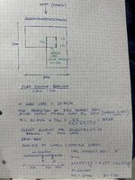
I have tried to account for this by using a beam analogy but am finding that all of the wind load is applied to the central bay.

My working is attached.

Thanks
 

Attachments

  • IMG_6805.jpeg
    IMG_6805.jpeg
    3 MB · Views: 21
  • Critiqued-Answer-Script-February-2023 (5).pdf
    2.8 MB · Views: 10
Replies continue below

Recommended for you

Your calculation is correct and is evident by inspection given there is equal load on each side of A

However your beam analogy approach is too simplistic to give a final answer. Neither A nor B are fully rigid. So all the load on A is also incorrect. Deflection of A will cause some of the wind load to come onto B. The result will be torsional in plan view as the bracing in plan is eccentric to the wind load.

I can't really help your further as I don't know what the examination is really after. It probably is just after a recognition that the braced bay is eccentric.
 
Statically determinate structures theoretically unaffected by support stiffness or settlement. What beam analysis misses is flexibility of beam. If all reaction is at A then beam has to be infinitely stiff not to load B.

Maybe you've ignored floor diaphragm in your analysis? Core will move laterally and rotate due to eccentricity of load from centre of stiffness. That causes stress in transverse bracing. When braces contribute to both X and Z direction resistance then you need to check 45 degree case. That was the problem with that New York building that had to be retrofitted in secret.
 
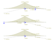
Even with a flexible beam the deflections are still indeterminant. As the setup is essentially a balanced seesaw, (teeter totter). Thus you need a 0 load to move it to a different deflection outcome. This is shown below in 3 circumstances of different locations of the 'B' support. In the final example the B support isn't present at all.

There are various deflection outcomes, but one moment and reaction outcome when the position of B is changed.
1732453179680.png
 
This is an interesting thread when the enhanced computers and softwares are available. In order to account the eccentricity , you are expected to find the center of rigidity . As far as i remember , for your case , assuming reasonable storey height ,the braced walls can be modelled as shear elements and neglect the flexural stiffness . Another assumption , the walls are the same thickness , the calculations could be based on length of the walls .
In your case , finding the X coordinate of the rigidity center would be sufficient and ,
X= (7.5*15+2*2.5*22.5)/(7.5+2*2.5) X bar = 18 m from the left side. Torsional moment of the wind Mt=20*30*3=1800kN-m ( counterclockwise at the rigidity center )

Polar moment of inertia of the wall 7.5 m wall Jp1= 7.5*3**2 =67.5 m**3
Polar moment of inertia of the wall 2.5 m wall Jp1= 2.5*4.5**2 =50.6 m**3
Total Jp=67.5+2*50.6=169 m3

The shear force at 7.5 m wall V= 20*30*7.5/12.5+ 1800*7.5*3/169 =360+240
The shear force at 2.5 m wall V= 20*30*2.5/12.5 - 1800*2.5*4.5/169 =120-120

Your simply supported beam approach seems reasonable .
But, AFAIK , this type of calculations were performed at King V. Georges era.

PS; i did not check the calculation for any error.
 
Last edited:
@human909 Thanks. I remember now. The same thing came up last year except for a U shape frame. Shouldn't have doubted statics.
 
Thanks. I remember now. The same thing came up last year except for a U shape frame. Shouldn't have doubted statics.
No problems. Doubt is good and you had me doubting things a little bit too. In this case it is a little confusing because it can seem a little absurd that the translationally fixed point of B makes no difference to the reactions nor the bending moment diagram. Yet common sense or computer analysis would show that it clearly influences deflections.

From a mathematical point of view it is a redundant equations for the forces. But it is a necessary boundary condition for determining displacement. I think the seesaw analogy works well.
 
Status
Not open for further replies.

Part and Inventory Search

Sponsor