Eng-Tips is the largest engineering community on the Internet

Intelligent Work Forums for Engineering Professionals

Built-Up Beam Member Canadian Codes

Status
Not open for further replies.

matty54

Industrial
Feb 10, 2022
65
0
0
CA
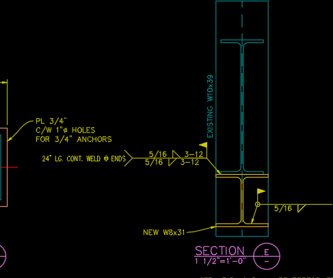
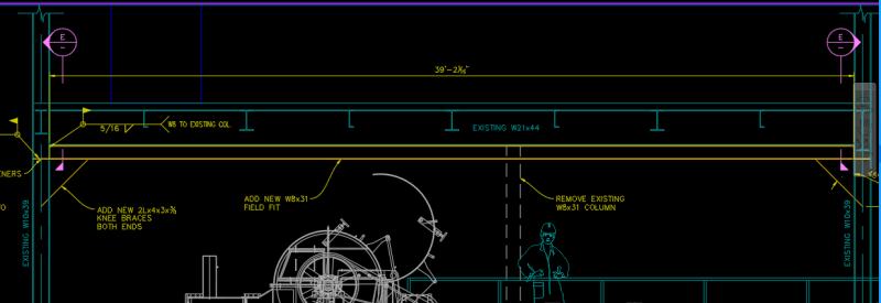
Hi, I am having a hard time trying to find any Canadian codes that refer to the design of built up beam members. CISC S16 just refers to either compression members or tension members or members side-by-side, but I can't find anything for beam members on top of each other. Also with CSA W59 it refers to either compression members or tension members. Do any of these codes apply to the case when you have a large W-shape beam and reinforce the bottom flange by welding a smaller member on?
 
Replies continue below

Recommended for you

I have new medication that is started to significantly effect me today so this may be totally baffed. But IIRC they both apply in the usual way but you have additional provisions in S16 - (CL 19) Built Up Members. The separation between tension/compression members would just be applied the compression / tension sides of a beam in flexure if that's what you have.

Capture_xiizta.png
 
Matty, what built up shape are you designing?

If you are designing a cover plated section, refer to clause 14.
This clause will provide information necessary to design the fastening/welds, and provide some proportioning limits.

For flexural strength, singly symmetric shapes can be designed with cl. 13.5 and 13.6.

I recommend watching this video for info on designing reinforced beams:

It is from ASIC but is still applicable
 
Ok that is what I was wondering, if you just apply the requirements of the compression members to the compression side of the beam in flexure. I didn't see Clause 14.2.3 which I believe is saying the same thing:

Capture3_h7qtrp.png


CDLD, see the pic below. It is a W8 underneath a W21. So All the codes only describe what you do with cover plates, but I imagine I would just treat the Entire W8 Section as a cover plate? I don't really understand what 14.2.2 is talking about with limiting the cross sectional area of the cover plate not to exceed 70% of the total flange area?? That makes no sense to me because you would only be able to get a small amount of reinforcing if you did that.

Capture_fp0slm.png


Capture2_h7zll1.png
 
That provision appears to only apply to bolted up girders, you have a welded girder.

If you are worried about the proportioning, I would also design by AISC since their code is more advanced.
Screenshot_2024-05-13_110932_qtt1fx.png

It is specifically more advanced in regards to web plastification (F4-6).

It appears you are designing for fixity at the ends, keep in mind you have compression in the bottom flange which should be checked for local buckling.
Another check which is often missed is the following:
Screenshot_2024-05-13_111254_dttcfe.png
 
thanks for this info. In regards to the 70% clause for bolted girders (even though it doesn't apply to my case) I still don't see why that clause exists. So if I were to use bolting instead of welding I can't bolt anything larger than the existing flange? I wonder why that is.
 
The way I read it, the total flange area includes the cover plate area, but it isn't written very clearly.

This would mean you could have a cover pl 10"X2.25" for a 10X1" flange.
I also don't understand the intent of this clause - more information should be provided.
 
Status
Not open for further replies.
Back
Top