flashyyc
Structural
- Nov 28, 2018
- 5
Hi All,
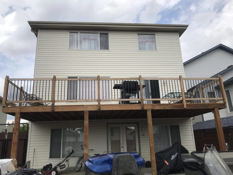
I am looking at a possible repair of a built-up beam. Upon inspection by the city, it was noted that some of the splice locations weren't code compliant and recommended to either tear the whole thing down and start over or ask some structural engineering guidance. That is where I come in.
Some notes:
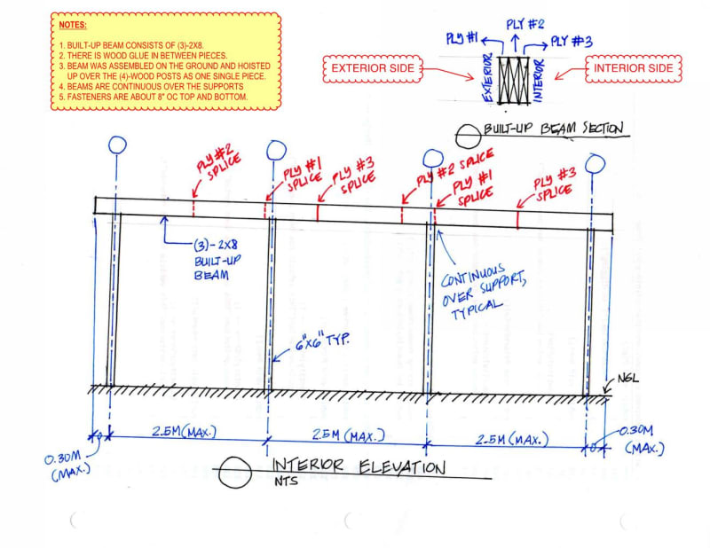
1. Built-up beam consists of (3)-2x8.
2. Beam pieces are glued together in between.
3. Beam was assembled on the ground and hoisted up over the (4)-wood posts as one single piece.
4. Beams are continuous over the supports.
5. Wood posts are 6x6.
6. Built-up pieces fastened together top and bottom @ 8" oc (quite conservative).
7. Homeowner was wise enough to at least build the beam so that there aren't more than 1 splice locations at any single span.
The homeowner has stressed that he prefers a structural solution that does not involve removing joist hangers as that amounts to a lot of work and ruins the deck altogether. I've come up with a few solutions:
1. A new built-up header consisting of (3)-2x8's installed underneath the existing beam and fixed in place with clip angles with fasteners. Probably some knee-bracing at both ends if the clip angle connection is inadequate. Plus a few vertical metal straps between the existing and new header. My concern with this strategy is that the two beams may in time shrink/expand both in different amounts and different directions which may result in serviceability problems.
2. A steel plate fastened to the bottom and supported with clip angles at the ends. A few vertical straps to the existing beam. Probably a knee bracing too. This is really just to compensate the loss of shear/bending strength at critical splice locations.
3. Similar to item #1 but instead of wood, an HSS header.
I would appreciate any comments or better yet, any other solutions along these lines.
I am looking at a possible repair of a built-up beam. Upon inspection by the city, it was noted that some of the splice locations weren't code compliant and recommended to either tear the whole thing down and start over or ask some structural engineering guidance. That is where I come in.
Some notes:
1. Built-up beam consists of (3)-2x8.
2. Beam pieces are glued together in between.
3. Beam was assembled on the ground and hoisted up over the (4)-wood posts as one single piece.
4. Beams are continuous over the supports.
5. Wood posts are 6x6.
6. Built-up pieces fastened together top and bottom @ 8" oc (quite conservative).
7. Homeowner was wise enough to at least build the beam so that there aren't more than 1 splice locations at any single span.
The homeowner has stressed that he prefers a structural solution that does not involve removing joist hangers as that amounts to a lot of work and ruins the deck altogether. I've come up with a few solutions:
1. A new built-up header consisting of (3)-2x8's installed underneath the existing beam and fixed in place with clip angles with fasteners. Probably some knee-bracing at both ends if the clip angle connection is inadequate. Plus a few vertical metal straps between the existing and new header. My concern with this strategy is that the two beams may in time shrink/expand both in different amounts and different directions which may result in serviceability problems.
2. A steel plate fastened to the bottom and supported with clip angles at the ends. A few vertical straps to the existing beam. Probably a knee bracing too. This is really just to compensate the loss of shear/bending strength at critical splice locations.
3. Similar to item #1 but instead of wood, an HSS header.
I would appreciate any comments or better yet, any other solutions along these lines.