Eng-Tips is the largest engineering community on the Internet

Intelligent Work Forums for Engineering Professionals

Built-up Cold-Formed Girt Stitch Fasteners

Status
Not open for further replies.

waytsh

Structural
Jun 10, 2004
371
0
16
US
Hi All,

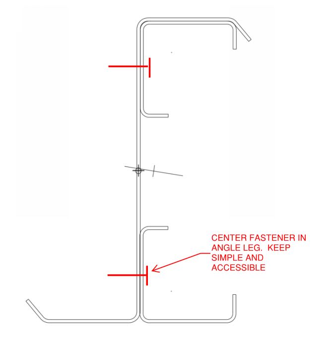
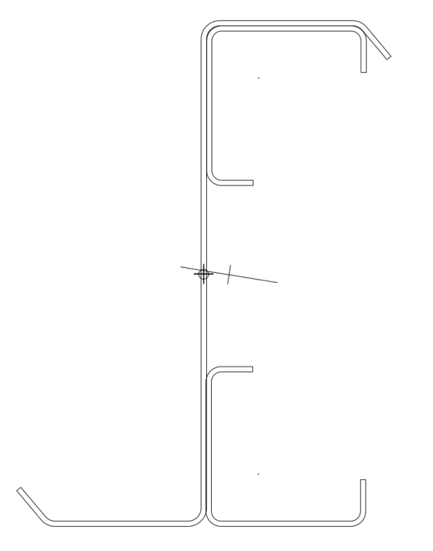
I need to reinforce a cold-formed z-girt that is only accessible from one side. Due to brace rods passing through the center of the web I need to limit the reinforcing to the outer portions of the girt. I am planning on using self-drillers to connect the angles to the girt. I am curious how you guys would approach determining the demand on the fasteners and how to best locate them.

waysth

Reinforced_Z-Girt_yfe9f0.png
 
Replies continue below

Recommended for you

Waytsh:
Well, basically it is a built-up section problem, you started with a “zee” section and then added cold formed sections near the top and bottom extreme fibers of the existing “zee” section. As far as connecting the new elements to the existing section, this is basically a shear flow problem. You know the shear cap’y. of each of your self-drilling screws, as a function of screw size, material thicknesses and material strengths, plus some FoS (factor of safety), through testing and supplier’s spec. sheets, etc. You know the shear at any given location on the purlin, so you can find spacing of the screws at that location to satisfy the shear flow at that location. But, it is not really quite that simple, since you are dealing with thin, cold formed sections, and combining them to act as one integral unit. You will also have to pay some attention to thin elements and stiffened vs. non-stiffened elements and their potential for buckling. You better dig out some good Strength of Materials, Theory of Elasticity, Cold-Formed Steel Structures text books. Also, AISC manuals should be of some help, but the real governing stds. are those of AISI for Cold Formed Steel Design, since these thin structural elements behave slightly differently than what we normally think of as structural steel.
 
I agree with everything that my predecessors here have said. Strictly speaking, fastener demand has two vector components:

A) The vertical shear required to force the reinforcing angles into the same deflected shape as the the girt without enforcing axial strain compatibility. This won't be negligible here as your reinforcing pieces have meaningful Ix in their own right.

B) The horizontal shear required to force axial strain compatibility (VQ/It).

If you've got some good section analysis software and the sections drawn in CAD already, you might be able to execute that reasonably quickly. Working by hand, I'd take a simplified approach as follows:

1) Calculate the max stress in the reinforcing bits at the extreme fibers.

2) Pretend that the stress from #1 is uniformly applied over the whole cross section of the reinforcing bits.

3) Use #2 to work out a conservative estimate of total axial force developed in the reinforcing bits.

4) Distribute #3 along the length of the girt in a manner consistent with the shape of the shear diagram (linearly varying for uniform load).

5) Ignore the vertical shear component because it's probably pretty small compared to the horizontal.

6) If this answer seems nuts, go back and do something fancier.

Families need to be fed after all. Extraneous sport engineering is best done in one's head.

c01_i9wlmi.jpg
 
Status
Not open for further replies.
Back
Top