Continue to Site

Eng-Tips is the largest engineering community on the Internet

Intelligent Work Forums for Engineering Professionals

  • Congratulations KootK on being selected by the Eng-Tips community for having the most helpful posts in the forums last week. Way to Go!

Built-Up Shape - Weld or Bolt 1

Status
Not open for further replies.

RaptorEIT

Structural
Feb 7, 2019
34
I have a continuous W12x53 steel beam that spans 50' over four supports. The steel beam will have a steel C12x20.7 channel placed on top of it to create a "track" to move a load out of a building. See the attached sketch.

I have sized the beam to handle the entire load without considering the channel being there. The channel is only there to prevent the load from rolling off the side of the beam. My question is whether to weld or bolt the channel to the beam. I followed Blodgett's method of sizing stitch welds for built up plate girders to size the stitch welds between the channel and the beam. However, since the channel isn't needed to contribute to the strength of the beam, I am wondering whether this is really necessary or overkill. I calculated that I need 50% of weld area, which yields 25' of weld on each side!

I'm thinking it best instead to bolt the channel to the beam at each end of the track. I'm worried that the beam will break the bolts as it deflects and prys at the bolts, though. Anyone have thoughts or recommendations on this?

Thank you.
 
 https://files.engineering.com/getfile.aspx?folder=4cd6f6fb-3a74-4112-981d-8f9770c09c08&file=Built-Shape.docx
Replies continue below

Recommended for you

If you don't want them working together then bolts with slotted holes might be a possibility.

A few side comments:
1. Your triangle fillet weld symbol is backward.
2. The weld size shouldn't typically have the inches " symbol used.
3. Stitch welds 6 inches long at a 12" spacing seems like way overkill but I haven't checked Blodgett's method.

Check out Eng-Tips Forum's Policies here:
faq731-376
 
JAE: Thank you for catching that. Slotted holes sounds like a better option.

Question:

On the topic of slotted holes... The beam is supported by four columns with cap plates. Each cap plate has four bolt holes, placed within the beam flanges, to bolt to the bottom flange of the I-beam. The I-beam has four long-slot holes for a 3/4" bolt. I've attached a sketch of this also. Can I treat this as a pin-connection? I need to limit the amount of moment transferred to the column, because I'm concerned about breaking the cap plate welds based on the moment at each joint.

Thank you.
 
 https://files.engineering.com/getfile.aspx?folder=e460815e-ba67-4a52-b5ca-6f1f78aedab3&file=SLOTTED_HOLE_SKETCH.docx
Depends on the thickness and hence flexibility of the cap plate (which you have not provided?).

Due to the continuity of the beam there will be tension/compression forces acting on each support tower columns, so often the quandary in these situations is you size the plate for the tension force and this makes it sufficiently thick that it also has significant moment capacity and acts less pin like and more rigid/semi-rigid like as a result. Work through the requirement and make an evaluation of the capacity of the cap plate and the moment it can transfer.

One other school of thought on the original problem is to size both the channel and beam as being composite for the load, this might save some material on the beam. But I'd tend to think the welding might offset this. I'd second JAE that the weld seems to be quite significant compared with my own experiences, usually this type of thing results in a tiny weld being required to address the shear flow when attaching to the flanges. So usually ends up being minimum weld size at more generous spacings. Note also some codes require for intermittent welds some continuous length of weld at the ends of the members to develop the force into the members, so look into your own code if this might be required if you end up using the welded scenario.

If its outside a building also think about the water that might pool in this detail, especially if the surface is trafficked by wheels which might break down any paint system, its a good recipe for accelerated corrosion.

Is it a crane runway that might be subject to fatigue concerns? Or just used intermittently where this might not be an issue?
 
If this is acting like a track, would bolts be in the way of what is trying to move along this track?

Also, is the beam braced in any way by a floor diaphragm or if is just out in space? What is the unbraced length you are considering? You may want to count on the channel to help improve the LTB capacity of the beam depending on how things are framed. You also should consider stiffeners in the beam for the column for stability.
 
One other point on the cap plates, if these connections are providing the fixity/bracing to prevent lateral torsional buckling, then they need to be stiff enough to achieve this restraint. This suggests its more 'fixed' than 'pinned' being required.
 
Agent666: I plan to use a 1/2" thick cap plate. From the shear-moment diagram I drew for the continuous beam, I picked the worst-case moment at each of the support locations to use in the analysis of the weld that connects the column to the cap plate, as well as the bolts connecting the cap plate to the bottom beam flange. The moment exceeded the capacity of an all-around 3/16" fillet weld. (I am using two 20 kip wheel loads spaced at 10' on each beam). I didn't know how much moment would actually transfer to the columns using the slotted hole configuration. I would like as little moment to transfer as possible, since I have designed the columns as seeing only axial loads, part of a braced frame system.

The formula I used to size the weld was: Horizontal shear stress T = VQ/I. Since the external shear is relatively high in comparison to the Q and I terms, I get a shear force that is roughly 1/2 the allowable for an E60xx fillet weld. The percentage of weld length I need is then 50%.

structSU10: The beam is acting as a track, but I could place the bolts at the ends of each beam and they would not interfere with the load path. (I have a pull-point stub-up column with pad-eye that will be used to pull the load along the path, so the entire travel path is from the left-most column to the right-most column. This is just for a temporary equipment removal. I have diagonal bracing at 10' spacing between each of the beams to account for LTB.
 
If you have concerns about the cap plate, that would argue in favor of making the beam and channel composite, to limit the deflection of the beam and hence the rotation at the column connections. Can you leave the bolts at the cap plate loose to create a truly pinned condition?

For what you would be welding, compared to the bridge girders we do, the weld seems quite excessive. For calculating the required weld or number of bolts for it as a composite section, it's just V * Q / I for the force, then divided by the weld or bolt capacity for the length or spacing.
 
I did some rough section property calcs and assumed a shear load of 25 kips. For my calcs, I have V = 25 k, Q = 28.3 in^3, I = 610 in^4, and a factored shear capacity of 33.6 ksi for the weld metal. For a pair of 1/4" welds, I calc the required welds at 1" long for every 10" along the beam.

Edit: For reference I got T = 1.16 k/in.
 
Raptor77R:
Are you going to have something like Hillman rollers or larger steel caster wheels of some sort running down the inside of the channel? Web crippling and web bearing stresses under the rollers should be checked. It is usually a good idea that the inside of the channel not be too much wider than the rollers. Things steer better if they can’t wander too much. How are you going to move the load lengthwise on the rail system? You certainly can’t just get by with bolts at both ends and expect the two members to stay together in this kind of operation, and over that length. And, as soon as you weld the two together, they will act as a built-up member, so you might just as well design and size the beam with that in mind and then design the weld for that situation too. The .25” fillet stitch weld, 6” at 12 o/c is probably larger than it has to be, and is more work and more time consuming, layout, welding time and inspection and all, and likely more weld material too than a lighter continuous weld, which can be made with semi-automatic welding equip. Ask you fabricator about this. I would space the columns to give the same beam bending moments +/- and you will likely want some web stiffeners over the columns. You could also have some overall stability problems which need some attention. How high are the columns and is there another parallel beam line? What are the loads, dimensions, etc. and what are the actual wheel, roller or trolley arrangement? You may ignore that the channel is there, but the structure and whole operating system will not, if the interconnection causes any ill effects.
 
Even with loose bolts at the cap plate you would never get a "truly pinned connection" in my view.
The rotation would push down on the cap plate edge and pull up eventually on the bolts - or you'd have an eccentrically applied load to the column with any rotation at all.

It would be best to analyze the beam and column arrangement as though they are fixed together. As HotRod10 suggests, making the channel composite with the beam will increase your overall beam stiffness and reduce moments going into the column.

Check out Eng-Tips Forum's Policies here:
faq731-376
 
If the wheels can wander as dhengr eluded to, don't ignore the torsion created either from this effect. Making the channel composite with the beam will add some benefit in this respect, increasing the torsional stiffness.
 
HotRod10: I calculated T = 1.69 k/in. (V=22k, I=635in^4, Q=48.64in^3). From there I divided that by the two welds to get a shear force of 843 lbs/in. I then divided this by the allowable shear stress of 9600w, to get a required continuous weld leg size of .088". If I use a 1/4" fillet weld, then the intermittent fillet weld percentage is .088"/.25" *100% = 35%. I then used 50% for conservatism. Where did I go wrong in the weld calculation to get such a higher percentage than you did?

dhengr: Yes, I am placing Hilman rollers under each leg of the load. The channel "T" dimension is 1/2" wider than the Hilman roller to limit lateral travel. The load will be pulled along the path using a chainfall attached to pad-eyes at each end of the beam. The beam has a slight overhang at each end to allow space for the pad-eyes. I agree that this is an awful lot of welding, and I don't even need it for strength purposes but just needed a way to create the track and prevent the Hilman from rolling off the beam. I thought I might could do away with the welding since I'm not relying on the channel for strength and instead just bolt it at the ends. But now that I am thinking about that, a point load at the middle of the beam would create a very large moment on each bolt group. This is why it wouldn't work, correct? Due to space limitations, the columns had to be placed at their exact locations. The two left columns are 3' tall and the two right columns are 18' tall. One set of columns is inside the building and the other are at grade outside. There is another parallel beam line and lateral bracing between each beam. Each plane of the frame structure is braced for lateral loads. I used a 2kip lateral load based on the tugging on the frame by the chainfall, and then applied wind loading also.

JAE: Just for my understanding, what sort of connection could I have for this arrangement that would yield a pin connection? Is there any way to achieve this since it is a continuous beam that has a moment transferring across this support point?

Thank you all very much for your insight.
 
Raptor77R said:
From there I divided that by the two welds to get a shear force of 843 lbs/in.

A 1/4" weld should have upwards of 5000 lb/in capacity. So maybe a 2" stitch every 12" or something.
 
Your Q value is almost twice what I came up with. I used the area of the channel and 'y' as the distance from the beam top of top flange to the NA of the composite section.

The major difference seems to be in getting from the force to the required weld leg size. Using your 0.843 value for 'T', I still get much lower required weld size. I used 70ksi ultimate weld metal strength, giving me a factored strength of 33.6ksi (70 * 0.6 * 0.8). 0.843k/in / 33.6ksi = .0251in (required throat depth). Required weld size = .0251" / (COS 45) = 0.0355". Required 1/4" weld length per ft = 0.0355" / 0.25" * 12 = 1.7" per ft.

That's how we do it per AASHTO LRFD. With the load factor of 1.75 for live load, your 22k becomes 38.5k design load. With my 'Q' and 'I' values, T = 1.786, weld size = .0376, and weld length required per ft = 1.81".
 
Raptor77R said:
Can I treat this as a pin-connection? I need to limit the amount of moment transferred to the column, because I'm concerned about breaking the cap plate welds based on the moment at each joint.

I'm confused by the discussion on this so far. For the sake of column and cap plate design, it never even would have occurred to me to consider this anything other than pinned. What am I missing Here? The logic in calling something a pin usually has less to do with it permitting free rotation (few things do) and more to do with the joint drawing little moment because of relative stiffness compared to other parts of the system. Here, with pairs of closely spaced columns, any beam moment is going to get delivered to pairs of columns as a T/C couple rather than moment on individual columns. At least that should be the case if OP's sketches are reliably proportional. All that said, this would be easy enough to test my modelling the frame with the beam and column joints fixed.

Raptor77B said:
I picked the worst-case moment at each of the support locations to use in the analysis of the weld that connects the column to the cap plate, as well as the bolts connecting the cap plate to the bottom beam flange.

Do correct me if I'm wrong but, to me, this sounds as though you're looking at the weld as though the cap plate were made flexurally composite with the beam? If so, I also feel that such a check is unnecessary/inappropriate. Firstly, any continuous weld should give you way more capacity than you need if there were composite action. Secondly, even in steel, it takes some physical distance for the composite action to be generated. I don't see this happening over the length of a column cap plate.
 
KootK said:
...and more to do with the joint drawing little moment because of relative stiffness compared to other parts of the system.

That is my assertion as well. The typical column cap plate with bolts or welds to a beam on top is not really a pin at all but because the columns many times are smaller pipes or tubes relative to the beams, the amount of moment that gets into the column can be fairly small. That doesn't mean you can ignore it though as it can affect the true P/P + M/M unity of the member.


Check out Eng-Tips Forum's Policies here:
faq731-376
 
JAE said:
That doesn't mean you can ignore it though...

I think it does. At least with some judgment thrown in. If I'm running a W24 over a TS6X6, there's no way in hell I'm checking moment on the column. I'm just picking that bad boy straight out of the axial load tables at 85% utilization and moving on to something more worthy of my attention.

With a stiff beam and slender column, you've really got three things in play (at least):

1) Relative stiffness affects moment draw, as we've discussed and;

2) Precisely because of partial fixity at the joint, you're K value will approach a fix-pin condition, increasing capacity.

3) Flexural tension will usually overcome axial pre-load fairly quickly. After that, you've got all of the flexibility of the flange, cap plate and bolts thrown into the mix.

The article blow deals with similar issues but, unfortunately, is not public domain like Game of Thrones.

c02_pqai3o.png
 
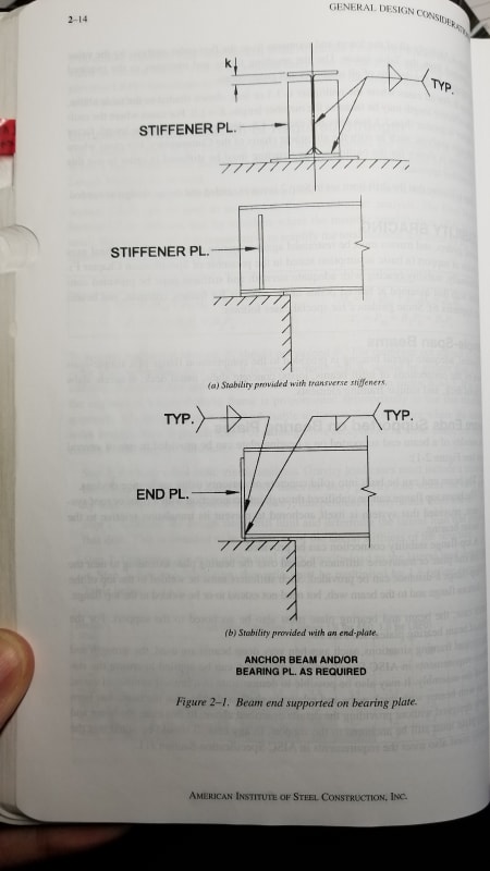
Make sure you provide a stiffener or end plate at all locations where you're considering lateral support for your beam.

2019-04-17_12.32.10_dvveox.jpg


Ian Riley, PE, SE
Professional Engineer (ME, NH, VT, CT, MA, FL) Structural Engineer (IL, HI)
 
KootK and JAE: I agree with both of you on this; but I think I agree with KootK more.

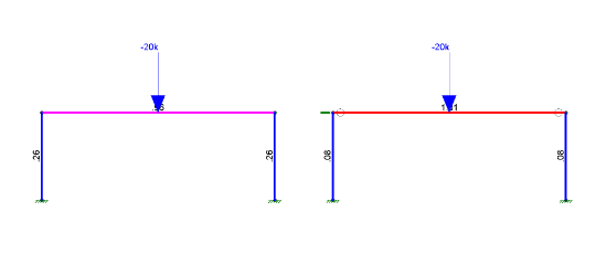
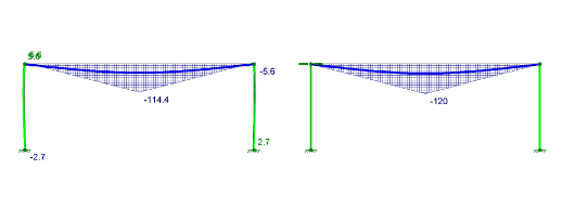
Made a quick RISA model with your exact concept (W24 and HSS6x6), one fixed (left), one pin-pin (right). Makes a difference for the column but the beam flexure is basically unaffected and the moment transferred is minor as JAE said. However, as KootK pointed out, I'd have to go to a stupidly light column size for this difference to overload the post. Unless my post is 20 ft long or some other non-typical condition this shouldn't have any issues and I agree that you can just add a little extra fudge factor into sizing your column and move on.

Capture_mv7noa.png


Capture2_e3xbni.png


I think the real area you need to check this is connection design. That small amount of moment might overload the connection at the beam to post.

Ian Riley, PE, SE
Professional Engineer (ME, NH, VT, CT, MA, FL) Structural Engineer (IL, HI)
 
Status
Not open for further replies.

Part and Inventory Search

Sponsor