Hello everybody
I'm Working on Representative Volume Elementary (RVE) of Aluminum Foam.
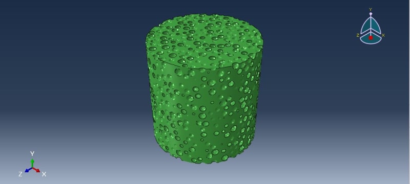
I generated the Geometry of a foam with %50 porosity.
The main goal is to mimic the experimental Stress-Strain Curve and get the same response of foam that was achieved in reality. Therefore, different combination of simulations carried out in Abaqus:
1. Part Module:
In reality, the generated foam radius is 21.5 mm and height is 35.7 mm.
For computational restriction, part is a cylinder with a radius of 1.5 mm and a height of 3 mm.

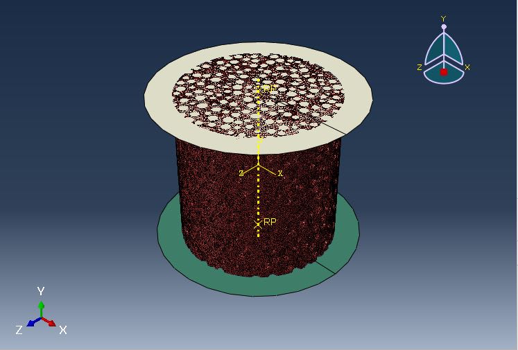
Note: In some simulation analytical, rigid body used to get desire stress-strain curve.

2. Property Module:
Typical Aluminum Property such as:
Young module: 74000 (MPa), Poisson Ration: 0.3, Yield Stress: 187 (MPa), ….
3. Step Module:
Different types of Solvers and steps like is carried out to find out what is wrong with the model:
Dynamic, Explicit: Time = 0.01 sec ≤ T ≤600 sec, NLgeom: ON
Static, Riks, NLgeom: ON
Static, General, NLgeom: ON
Carried out to get the desired results.
It’s obvious to get the stress-strain curve RF2 and U2 as history output requested from reference points, Then the proper calculation in visualization module is done:
Strain: U2/3
Stress: RF2/(3.14*1.5*1.5)
4. Interaction Module:
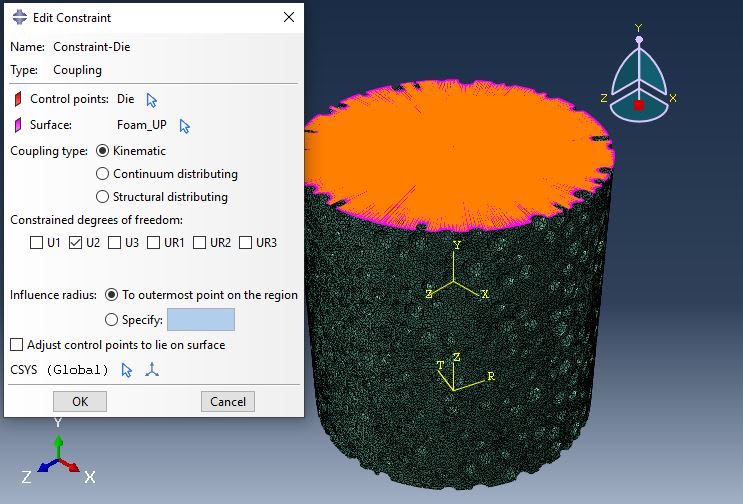
Depending on simulation type (rigid body used or Upper and bottom face of foam Couple to regarded reference points), Contact or/and Coupling constrain added.
Like:

5. Load Module:
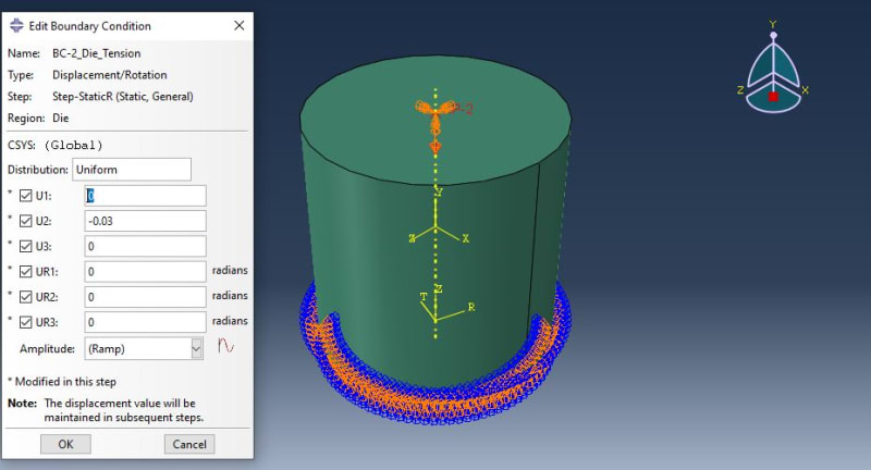
Bottom of the Foam, Surface or regarded reference point, fully constrained (All DOF closed).
Up surface of the foam, experience displacement in U2 (Y) direction with rigid body movement that has contact with it or reference point displacement. Depending on simulation, the amount of this displacement varies from 0.03 mm to 1.5 mm.
6. Mesh Module:
Element library is: C3D4
7. Visualization Module
Experimental results dictated that:
Young Module should be: 2.3 to 2.8 GPa.
Ultimate Tensile Stress should be: 120 to 130 Mpa
Approximately in all simulations:
Young Module is ≈ 43000 Mpa
Ultimate Tensile Stress is ≈ 150 Mpa
Result’s:
There is a Huge Gap in Young Modules !
Therefore, after so many tries and errors, finally the Static simulation of Foam with Displacement of -0.03 in U2 direction, replaced with Same Size of Bulk cylinder to evaluate our approach or faults.
Every aspect of the model is the same, just geometry replaced with the same size (radius 1.5 and height 3) bulk cylinder.

Simulation for bulk cylinder carried-out and young module is 76000MPa, which is in good correlation with abaqus input property (Young module: 74000 (MPa).
Now the main question is how the same simulation with the same pattern for bulk material gives correct young modules, but for foam material, young modules give excessive amounts of deviation from experimental ?
With best regards.
Yassou.
I'm Working on Representative Volume Elementary (RVE) of Aluminum Foam.
I generated the Geometry of a foam with %50 porosity.
The main goal is to mimic the experimental Stress-Strain Curve and get the same response of foam that was achieved in reality. Therefore, different combination of simulations carried out in Abaqus:
1. Part Module:
In reality, the generated foam radius is 21.5 mm and height is 35.7 mm.
For computational restriction, part is a cylinder with a radius of 1.5 mm and a height of 3 mm.

Note: In some simulation analytical, rigid body used to get desire stress-strain curve.

2. Property Module:
Typical Aluminum Property such as:
Young module: 74000 (MPa), Poisson Ration: 0.3, Yield Stress: 187 (MPa), ….
3. Step Module:
Different types of Solvers and steps like is carried out to find out what is wrong with the model:
Dynamic, Explicit: Time = 0.01 sec ≤ T ≤600 sec, NLgeom: ON
Static, Riks, NLgeom: ON
Static, General, NLgeom: ON
Carried out to get the desired results.
It’s obvious to get the stress-strain curve RF2 and U2 as history output requested from reference points, Then the proper calculation in visualization module is done:
Strain: U2/3
Stress: RF2/(3.14*1.5*1.5)
4. Interaction Module:
Depending on simulation type (rigid body used or Upper and bottom face of foam Couple to regarded reference points), Contact or/and Coupling constrain added.
Like:

5. Load Module:
Bottom of the Foam, Surface or regarded reference point, fully constrained (All DOF closed).
Up surface of the foam, experience displacement in U2 (Y) direction with rigid body movement that has contact with it or reference point displacement. Depending on simulation, the amount of this displacement varies from 0.03 mm to 1.5 mm.
6. Mesh Module:
Element library is: C3D4
7. Visualization Module
Experimental results dictated that:
Young Module should be: 2.3 to 2.8 GPa.
Ultimate Tensile Stress should be: 120 to 130 Mpa
Approximately in all simulations:
Young Module is ≈ 43000 Mpa
Ultimate Tensile Stress is ≈ 150 Mpa
Result’s:
There is a Huge Gap in Young Modules !
Therefore, after so many tries and errors, finally the Static simulation of Foam with Displacement of -0.03 in U2 direction, replaced with Same Size of Bulk cylinder to evaluate our approach or faults.
Every aspect of the model is the same, just geometry replaced with the same size (radius 1.5 and height 3) bulk cylinder.

Simulation for bulk cylinder carried-out and young module is 76000MPa, which is in good correlation with abaqus input property (Young module: 74000 (MPa).
Now the main question is how the same simulation with the same pattern for bulk material gives correct young modules, but for foam material, young modules give excessive amounts of deviation from experimental ?
With best regards.
Yassou.
