Continue to Site

Eng-Tips is the largest engineering community on the Internet

Intelligent Work Forums for Engineering Professionals

  • Congratulations KootK on being selected by the Eng-Tips community for having the most helpful posts in the forums last week. Way to Go!

Bump size

Status
Not open for further replies.

gabimo

Mechanical
May 2, 2013
124
Question regarding ASME Y14.5-1994 or 2009.

Feature of size 100 ±.005
Circular runout within .002 to a datum axis.

How tall a bump is acceptable in the surface with the runout control?

How would you read and interpret the question: bump size to be measured within the same circular section or from one section to the adjacent one? Am I correct in saying that the answer is .002 if former interpretation is accepted and .010 if the latter one?

Please advise.


Replies continue below

Recommended for you

The former: 0.002 - I think is correct.
My answer regarding the latter is 0.007.
It has to do with the centering effect of circular runout. With perfect centering only 0.005 surface variation as result of the size limits is distributed equally around the datum axis. Another 0.002 is the error that runout allows. I may be missing something though.
 
It has to be added that circular runout by itself only controls bump size in each cross section separately. The size tolerance in combination with circular runout controls variation along the surface.
 
Seriously confusing question.
Runout does not control size, so I guess one cannot simply add half of size tolerance to the runout tolerance.
Runout is cumulative measurement combining out-of-round and out-of-coaxiality (and then some). Which part of it constitutes "bump"?
Size indirectly controls form, but we can have part with perfect 99.995 round cross-section, but bent out of shape to fill 100.005 envelope. Which part of this shape will constitute "bump"?
Are size and runout applied simultaneously to the same feature all the time or are we comparing size and runout applied separately?
Don't forget that circular runout applies to individual cross-sections and size to the entire part at once.
Sorry for confusing post and thank you whoever will clarify the situation. :)

"For every expert there is an equal and opposite expert"
Arthur C. Clarke Profiles of the future

 
CH said:
Runout does not control size, so I guess one cannot simply add half of size tolerance to the runout tolerance.

Circular runout does not control size but it does control form, and so does the size specification to some extent. Since a "bump" is a form irregularity, it can be said that the combination of size and runout limits the bump size. I'm not sure my calculation above is correct (in fact it is possible that maximum bump size is 0.005 now that I think of it again), but nevertheless, the value is determinable.
 
If you have an otherwise perfectly round and coaxial shaft with a 0.002 bump, that will use all of your available runout allowance. 0.002 is the biggest bump that could ever pass the specification. In reality, it would have to be less than that.

----------------------------------------

The Help for this program was created in Windows Help format, which depends on a feature that isn't included in this version of Windows.
 
I still think that the maximum bump height is 0.007 but my previous explanation was probably incorrect.
Here is a possibly correct description of a case with the maximum bump height:
Consider an almost uniform (except at the bump area) cylindrical surface of diameter 99.995 and perfect circularity. All the median points (except at the bump area) are offset 0.001 "below" the datum axis for runout control, which gives 0.002 full indicator movement. At the section where the peak of the bump is, the median point is offset by 0.001 "above" the datum axis, which also gives 0.002 full indicator movement, and the local size is 100.005. The height of the bump is half the size difference plus the sum of the median point offsets from the datum axis:
(100.005-99.995)÷2+0.001+0.001=0.007.
 
If the indicator goes across a bump 0.007 high it's going to read 0.007. Fails by 0.005. The nominal size has no influence on runout.

----------------------------------------

The Help for this program was created in Windows Help format, which depends on a feature that isn't included in this version of Windows.
 
dgallup,
What you said is relevant to total runout. Not to circular runout.
 
It is totally relevant to circular runout.

----------------------------------------

The Help for this program was created in Windows Help format, which depends on a feature that isn't included in this version of Windows.
 
In the scenario I described, the bump is created by surface variation along the axis. Circular runout is controlled at each cross-section separately and can't detect this variation. Maybe a figure would help. Sorry, but I can't make one currently.
 
I agree that a correct picture would be extremely helpful. Not sure where .007 size is coming from.
Looks like the book's answer does not take in consideration axial aspect of the form error, but only radial one. Not understanding why. Hence the "correct" book's answer is .002.
Sorry, I don't get the .007 calculation posted.
 
Maybe the book takes a simplistic approach and only requires to calculate the maximum local surface deviation that can directly be controlled by the circular runout control, at each cross-section separately. In that case, the diameter size specification is redundant.
I will try to make a figure explaining the .007 calculation and post it tomorrow.
 
gabimo,
Attached is a figure explaining the principle behind the .007 calculation above. I altered the numbers to make the bump more visible. Note that nowhere on the figure the circular runout full indicator movement exceeds the specification tolerance.
 
 https://files.engineering.com/getfile.aspx?folder=228a1ace-d1a7-45b8-9771-e04c08b1563f&file=RUNOUT_BUMP_SIZE.pdf
That is not what I would call a "bump in the surface". That is a ring or groove, not a bump.

----------------------------------------

The Help for this program was created in Windows Help format, which depends on a feature that isn't included in this version of Windows.
 
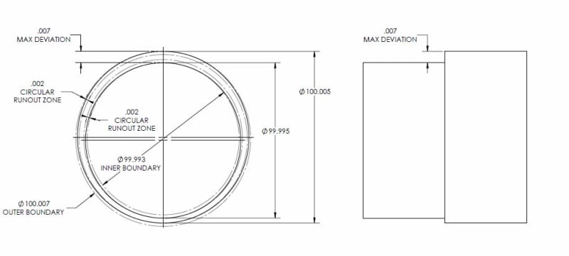
I am with CH on this - the use of the term "bump" is imprecise. If we take it to mean form deviation in each radial cross-section the limit is of course dictated by the circular runout tolerance. If we take it to mean form deviation along the entire axial length of the part, it is now dictated by a combination of the size tolerance and circular runout tolerance.

If we are to take the former definition the limit is .002 dictated by circular runout.

If we are to take the latter definition, I agree with Sem_D220's calculation. A more simple way to think about it is in terms of the feature's inner and outer boundaries. The allowable form deviation would be half the difference between the inner and outer boundaries.

Outer Boundary = 100.005 + .002 = 100.007
Inner Boundary = 99.995 - .002 = 99.993
Form Deviation = (100.007 - 99.993)/2 = .007

Note that this is the case because both extremes can exist simultaneously (ie: portions of the feature can touch each boundary) along the feature's length due to circular runout - the same would not be true of total runout.

See the figure I created below - I know the sharp transition is perhaps not realistic but hopefully exhibits my point well. It may not be clear from the figure but the 2x .002 circular runout zones shown are concentric to each other - this would be the datum axis.

*Edit: I should note, this is not to scale. As Sem_D220 noted, the tolerances utilized in the example are too small to see otherwise. The figure just graphically exhibits the calculations I showed.
circular_runout_-_max_deviation2_g52slr.jpg
 
Sem, gabimo,
I still don't understand the point of the exercise.
It is common knowledge that circular runout is less strict control than total runout, so circular runout cannot control all the aspects of a form.
The "bump" on the illustration will produce circular layout of 0.2, but total runout of 0.7
So the question "bump size to be measured within the same circular section or from one section to the adjacent one?" is sort of bogus - circular runout does not measure "from one section to the adjacent one", that's what total runout is for.

"For every expert there is an equal and opposite expert"
Arthur C. Clarke Profiles of the future

 
CH,
You make a good point, but since part of the data for the question was the size diameter and tolerance, I concluded (and perhaps gabimo did too?) that the question was not only about the circular runout, and that we are required to determine the maximum surface deviation that can occur as a result of the combination of the allowed tolerances.
 
The question about “bump size”, and as far as how I understood it (I can say that has been confusing for me too, but) I would go by “maximum possible variation between neighboring elements, surface elements, circular elements per the above print requirements: size tolerance ±.005 and circular runout .002” ).
 
Well, when the question is asked as: ”How tall a bump is acceptable….?”, I can see why someone thinks about two different way of measuring the tallness.

Tall= distance from the base of something to the top. The issue I see here is which is the base of measurement?

On a planar surface is no issue (as far as I can see), but on a cylindrical surface: is the base defined and taken within the same cross section (cross sections as defined in the derived median line straightness, to be normal to the unrelated actual mating envelope) or the base (origin of measurement) could be in a different cross section? I guess the book is not very clear, hence the question.


Status
Not open for further replies.

Part and Inventory Search

Sponsor