Continue to Site

Eng-Tips is the largest engineering community on the Internet

Intelligent Work Forums for Engineering Professionals

  • Congratulations GregLocock on being selected by the Eng-Tips community for having the most helpful posts in the forums last week. Way to Go!

Butt welding very thick plates - challenges, limitations, potential issues?

Status
Not open for further replies.

bugbus

Structural
Aug 14, 2018
509
I am working on a project involving some large steel box girder bridges with simply supported spans up to about ~43 m (~140 ft). Due to various constraints (i.e. very heavy loads, limited girder depth, simply supported, etc.), I am expecting rather thick flange plates, up to 60 mm (2.36") in some locations.

To achieve the required lengths, all the plates will need to be butt welded at various locations, including where the plate thickness changes.

Are there are any particular challenges or limitations of having such a thick butt weld (i.e. 60 mm or even more) that would affect the design or buildability? Exactly how thick of a plate can be butt welded? 100 mm?


Replies continue below

Recommended for you

Gusmurr:
Most any stl. pl. thickness can be butt welded, but it will be prepared, beveled edges butted together and filled with multiple weld passes. Either CJP welds for tension flgs. or PJP welds for some of the other welds. That’s exactly how you make up longer pls. or transitions in pl. thk. The thk. transition is filled and ground with a tapper from on thk. to the other.

 
gusmurr, I do far more PT concrete bridges than steel bridges but I will offer my two cents from my experience with steel bridges, anyway. 43m (140ft) is getting into that realm where shipping of a single piece box will probably not be feasible and I would anticipate having to field splice the tubs together onsite. This is the pain that us bridge engineers face (as compared to our vertical construction counterparts) as having a grasp on shipping, crane access, and lifting all play into the initial design from the beginning. The firm I work for has value engineered many many designs done by other firms that focus on buildings but tried to dabble in bridge design and ended up getting burned. It goes both ways, however, which is why I stay in my lane.

You, as the EOR, do not need to concern yourself with the issues related to shop splicing the plates together. Every shop is set up differently. Some can handle full length plates from the mill and others can't. Depending on their capacity, the shop will propose a CJP weld for any splices they need to fabricate your full length tub section when they submit the shop drawings.

As for your full length tub section, again, I would anticipate providing an "optional" bolted field splice detail (perhaps ~10m in from each abutment). You don't have the luxury of locating this at your inflection point so make sure that your design is robust enough to resist the anticipated demands. If, for some reason, the Contractor feels confident that they can ship the thing as one piece, then great... but the last thing you want is to find yourself in a position where your plans show it as a single box and the Contractor is telling you that they physically cannot construct it as such. The only places this "optional splice" detail will show up is on your elevation view and the splice detail sheet. Everything else should be the same. Just make sure to coordinate your bracing locations with the field splice. Because of this, you should not have to concern yourself with any butt welds of any sort (as your OP discussed).

Another note: Flange transitions in positive moment sections are typically uneconomical except for very long spans (which I would not consider yours to be). Therefore, I would plan on using one single flange thickness.

I highly recommend that you read the following published documents by FHWA (I know that you are from AU but there is still a lot of good information in there that answers a lot of your questions. I have found them tremendously helpful for the few steel bridges that I have designed.

Link
Link
 
Thanks to you both

STrctPono, regarding the splices, yes the bridge will likely come in 3 roughly equal length pieces and be spliced together on site before lifting. I would imagine typical bolted splices here. Part of the motivation for varying the flange thickness is to save on weight, which will be critical for the final girder lift.
 
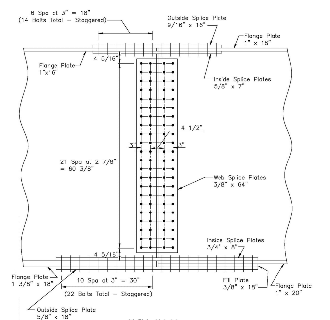
On further thought, I suppose another possibility is to transition the plate thickness at splice points (where possible), and use filler plates to make up the difference.
 
gusmurr said:
On further thought, I suppose another possibility is to transition the plate thickness at splice points (where possible), and use filler plates to make up the difference.

Yes. If you do decide to transition the flanges then that is the standard protocol. Something like this....

Capture_qkd1fs.png


Is this bridge curved? If not, have you considered plate I-girders over tubs? It would certainly help you out on your lifting weight issue.
 
Status
Not open for further replies.

Part and Inventory Search

Sponsor