Eng-Tips is the largest engineering community on the Internet

Intelligent Work Forums for Engineering Professionals

Butterfly Valve - Pipe Wear 2

Status
Not open for further replies.

TiCl4

Chemical
May 1, 2019
606
0
0
CA
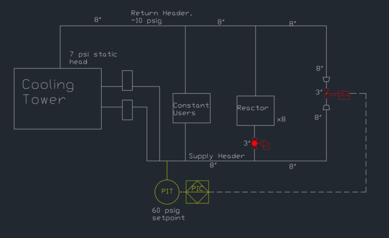
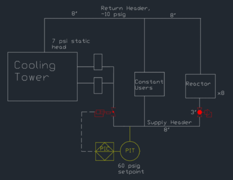
We have a 3" butterfly pressure control valve installed on a cooling tower water recirculation loop. This valve is controlled to a pressure setpoint from a pressure transmitter located at the outlet of the cooling tower water pumps (combined header). The cooling tower water loop has a mix of constant users and sporadic users. Normal operation at no sporadic user demand is ~65% open on the valve; however, this valve often operates 0-20% open during heavy user demand to maintain supply header pressure. Some operating data is below:

Valve: Bray Series 30/31, 3"
Pressure setpoint: 60 psig (at CTW pump outlet)
Valve Upstream pressure: 50 psig
Valve Downstream pressure: 10 psig
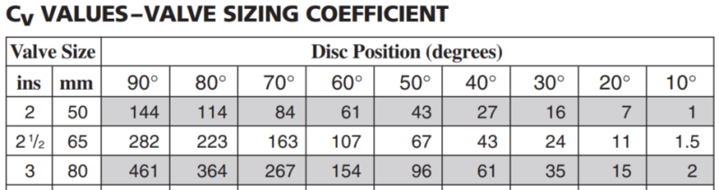
Cv (20,40,65) = 15, 61, 210
Water temperature: 75 F
Main header: 8", reduces to 3" for the control valve

The 3" schedule 40 carbon steel pipe (ASTM A53, I think?) developed pinhole leaks about 3 months after installation. The valve disc and body itself look fine, but the weld line of the downstream flange and 1-2" of piping beyond the flange were worn extremely thin. Orientation-wise, this is the area where flow is directed by a partially open butterfly valve.

The up/downstream pressure vary slightly based on demand, but dP across the valve is usually 40-45 psi. I don't have equivalent orifice size to get actual flow rates, but at 60% open the valve is flowing ~1,300 gpm. In a 3" open pipe that is ~58 fps. (I don't have data or an equation on equivalent orifice diameter, but a naive assumption of %open = % reduction in equivalent orifice size would put velocity more in the neighborhood of 90 fps through the valve itself. I think we are likely cavitating in the liquid as it accelerates through the valve, and the downstream piping is bearing the brunt of the damage.

I've had maintenance hardface a new spool with 3/16" tungsten carbide in the wear area to be replaced, but I'm also considering putting in an upstream orifice to lessen the dP required by the valve.

Does anyone have any suggestions or caveats for putting an orifice upstream - i.e. minimum pipe diameters needed to full flow re-establishment? Space is tight, so something like 20D isn't available unless I put an orifice in the main 8" before the reducer.
 
Replies continue below

Recommended for you

Is a butterfly valve the best choice for this extremely erosive service ?

Cooling tower water service is NOTORIOUS for erosion headaches because of debris and entrained air !!


Would another type of contol device be a better choice, rather than getting on the endless cycle of eternal repairs ?

Can you post pictures of the valve and closeups of the failed piping area ? ... What is the material of the failed piping ?

In the past, some engineers have decided to use thicker and more erosion resistant materials in the downstream piping... ( either Chrome -Moly or SS materials)

Please tell us more ...

MJCronin
Sr. Process Engineer
 
Well apart frpm the obvious here - you have the wrong valve for the duty - it lokos also to me like you need to think about how this system works and is controlled in general.

So why 60 psi set point?
Most re circ systems are there for min pump flow not pressure or is that your way of doing that according to the pump curve?

You shouldn't really be operating less than 25% open.
Try a V port ball or ARV.

But assuming you can't or don't want to change the system or valve, I would go for 5D min for a restriction orifice. You might need to stick in a flow conditioner disc before the valve and maybe stick one in straight after?

One of these.

Flow-Conditioner-Laying-Down-e1570654917626_g3the9.png


Remember - More details = better answers
Also: If you get a response it's polite to respond to it.
 
Does your butterfly have a flow control disc in it?
There are special ones that are used for this service.
And yes, I also question the control system.
Keeping the pump within its recommended operating range is the key here.

= = = = = = = = = = = = = = = = = = = =
P.E. Metallurgy, consulting work welcomed
 
Responding to all questions as best as I can.

To clarify, the control valve is not a minimum recirculation control valve. It is a pressure control valve located between the supply and return headers of the CTW loop that supplies a couple dozen users of cooling tower water. The constant users account for enough flow that a ARV is not required. When more users come on-line, the PCV shuts to maintain supply header pressure.

60 psig is the BEP of the CTW pumps, so the control system is set to attempt to maintain them at that point. System demand is ~700-800 gpm from constant users, and total demand can be as much as 3,000 gpm - near the end of the combined pump curve, but not off of it. OEM (Bray) recommends 25-70% open operating range, which we normally fall into. However, heavy use cases during peak demand sometimes call for the valve to close to less than 25% open to drive water to the users (reactor systems) rather than bypass into the return header.

This control scheme maintains constant source pressure so that reactor cooling control loops have a consistent response when cooling is open (i.e. when a reactor cooling control valve is open, having 60 psig all the time as supply pressure helps with tuning and process control). Before this change, CTW source pressure could be 65 psig or 40 psig, which made tuning the reactor control loops nigh impossible.

The original valve was a 6" butterfly of unknown origin. It never worked due to being oversized. The 30/31 Bray valve is intended for modulating service, but is a simple disc construction to allow for high Cv range. Other valves were considered in the replacement, including globe control valves. However, the area of installation is REALLY tight, and the required globe valve size (6") would not have fit without significant (costly) rework. So yes, I would have preferred to use a globe valve like we do elsewhere for flow control, but the project was DOA with the additional rework costs.

All in all, the valve is functioning as intended in the control scheme, but the pipe wear needs to be mitigated.

MJCronin, we've hardfaced the a new downstream spool of the valve with tungsten carbide and will be installing that soon.


Bray30-31_Cv_rrwlhd.png
 
TiCL4,

I realise you're asking a different question but would be good to see the pump curves as BEP is, as I'm sure you're aware, a place on the curve, not a pressure.

At the end of the day it's about power not BEP so even though it's not on BEP, if your pump flow is controlled to a lower flow, you probably use less power than recirculating loads of flow through your little butterfly valve. You can still control on pressure, but if your normal users are above the min flow then I don't fully understand why you actually need this valve instead of putting a CV d/s the pumps before the header. If you can get rid of the valve then it makes life a lot better for everyone.

Ever thought about a VFD?

Or what would happen e.g. if the min percent open was 25 then if it needed to go lower actually just went to 0 (closed) instead of trying to trickle through what must be a small amount. 1 psi? 2 psi? Once you got to say 65 psi or 64 then it opens back up to 25% as a single step?

Cavitation is incredibly damaging even to hard surfaced pipe so it might last longer, but you might be replacing this every year instead of every 3 months.

Always more than one way to skin the cat....


Remember - More details = better answers
Also: If you get a response it's polite to respond to it.
 
LittleInch said:
I don't fully understand why you actually need this valve instead of putting a CV d/s the pumps before the header.

Explain this part? I don't know the "CV d/s" term. Yes, I'm aware a BEP on a pump curve is a pressure at a certain flow. From a controls perspective, though, I can always ensure running on the BEP by maintaining discharge pressure fixed at a constant value.

Remember, the MAIN reason to have this valve is the need to maintain a constant source pressure for reactor control loops. Setting the header supply pressure higher means that high demand scenarios will run into issues with pressure dropping during high demand. 60 psig is already borderline for maintaining header pressure. We considered eliminating the valve, relying on the constant users to provide minimum flow. However, doing that would mean our header pressure would just go back to being uncontrolled and cause issues with the reactor cooling control loops. VFD control was also considered but didn't have the payback needed to justify the capital cost versus reduced electrical cost.

Lastly, I'm not sure that low % opens are causing the cavitation. This is an equal% valve, so low % open has (I think) a MUCH lower velocity through the opening than at higher percentages given a fixed dP. I.e. 20% open for us means 94 gpm through a 20% open valve versus 1,300 gpm through a 65% open valve. I'm not totally sure on that - I don't know the geometry of the opening area versus percent travel.[highlight #FFFFFF][/highlight]

Cooling_Pump_Curve_x2fick.png
 
Why don't you listen to the valve with a vibration sensor and see at what conditions you are cavitating?
If it is near closed then you could put in a small, fixed return line and close the valve when it gets down to 20% or so.
I would think that you are good with the pump. Is the power what you would expect?

= = = = = = = = = = = = = = = = = = = =
P.E. Metallurgy, consulting work welcomed
 
Sorry, Control valve downstream....

I'll have s look at this over the weekend.

But two pumps or three working at max flow?

Remember - More details = better answers
Also: If you get a response it's polite to respond to it.
 
Have a few moments today.

Basically in metric units at your 60 psi / 1100GPM you are using in shaft power about 36.5kW

If instead of this valve you instead placed a control valve ( butterfly would probably work here) d/s your pump but still control to 60 psi, then as the demand reduced the control valve would cut in to reduce pressure. Then although you're not at BEP, and you are generating more pressure, you at at much less flow.

So the shaft power reduces to approx 30kW.

So you get a 6.5kW saving all the time you're running at your "normal" flow. Depends how much time it operates like this and how much electricity costs, but it could be worth saving.

Plus you won't have to fix the 3" valve pipe.

BTW you are not correct about water velocity as you close the valve. There are some squared terms here and also at lower percent opening the flow is coming out very much sideways against the pipe wall. more open and it swirls a lot more around the disc. Also don't confuse percent open with degrees open in yur table. There may be only a small difference but it is important.

If nothing else think about what happens when you put your finger over the end of a hose to generate more velocity / force. The smaller the gap the greater the velocity.

Just a thought for you as sometimes you need to look at the bigger picture and that valve is just throwing money away, plus heating up your water a bit.

Remember - More details = better answers
Also: If you get a response it's polite to respond to it.
 
LI,

That's not a good analogy. You may be right, but it depends on the %orifice area available versus flow rate. The difference here as compared to your analogy is that in your analogy dP increases when you place your thumb over a hose end. In this case, dP remains the same (within a couple of psi) no matter what the valve position is. I agree about the angle of attack on the pipe wall being worse at lower %open, and concede that low% open is very likely worse for abrasion than 65% open.

Please describe what you mean by downstream pressure control valve. See sketch below for generic cooling loop setup. There are something like 25 user lines, so this is quite simplified.

We have two pumps in parallel. Each is 50 HP, so your calc on power draw is accurate.

Where exactly would you move the valve? All the reactor loops are designed with the ~40 psig available pressure drop to achieve required flow and control. As more reactors come on-line (batch process, so number of users is changing often), the header pressure drops. The PCV then adjusts to maintain pressure at 60 psig. The PCV MUST be downstream of all users to maintain a constant source pressure for each user. This is basic multi-user cooling loop design.

Cooling_Tower_Loop_-_Rough_Sketch_ntrqhs.png


Edit: Good catch on the degrees vs % open. I'm so used to looking at control valve charts as Cv versus percent travel I didn't see that.
 
Okay, I understand what you mean - I was thinking you meant putting the control valve downstream of the pressure sensor as well, but upstream of the users, and didn’t see what that accomplished. That would mean only about 9 psi dP available for the valve, so a larger butterfly could be used to avoid the cavitation.

It’s still an iffy thing, in my mind. That’s about 350 gpm per pump during low usage, which is quite far back on the curve. I need to look back at the oem manual to see minimum flow requirements. Otherwise it would also need a min recirc line.
 
How about replacing the 3inch carbon steel section with a 4inch or 6inch SS316 section, and install the restriction orifice downstream of this control valve. Get another 4inch butterfly control valve and let the restriction orifice burn up some 30-40psi of this drop. Locate the RO on the 8inch side. This control valve is in min flow - constant loop pressure service. You get better control of this if you change from pressure control to differential pressure control (dp between supply and return headers) - similar to controls on closed loop hot oil supply systems.
 
TiCL4,

Normally you're looking at 30 to 40% of BEP flowrate as min flow so at>50% you will be fine.

If it meant a recirculation line I agree, but I hate those as well....

Actually what is your inlet pressure into the pump?

Remember - More details = better answers
Also: If you get a response it's polite to respond to it.
 
LI,

Inlet pressure isn't measured directly, but the run is a approximately a 4-foot 12" suction line from cooling towers. Basin height is only 3', so likely 1 psig or so suction line pressure at pump inlet.

Also, we removed the 304SS temporary replacement spool to install the hard-faced spool piece. The 304SS spool showed no signs of wear, which is quite odd. Remember the original CS Schd 40 line wore through in approximately 3 months of operation. This spool was in service for 2.5 months with no visible wear.
 
OK, so differential pump head / pressure is basically the same as discharge pressure - just thought I'd check.

Your spool could easily be good for a few years - I guess it depends on how often you operate with it nearly closed, but as said, may amend the control loop so that it shuts when the PID loop says <25% open. Or put a min percent on it and then close it if the header pressure goes below say 55psi. or 57. But the valve on the pump discharge is the way to go IMHO.

Remember - More details = better answers
Also: If you get a response it's polite to respond to it.
 
Status
Not open for further replies.
Back
Top