Eng-Tips is the largest engineering community on the Internet

Intelligent Work Forums for Engineering Professionals

C-Hook for coil, materials

Status
Not open for further replies.

maxpcc

Mechanical
Nov 24, 2009
11
0
0
IT
Hello all,
I'm having some trouble with a C-hook for aluminum coils

My customer asked to verify the SWL of the hook. He made it using S355JR (510 MPa rupture, 355 MPa yield).
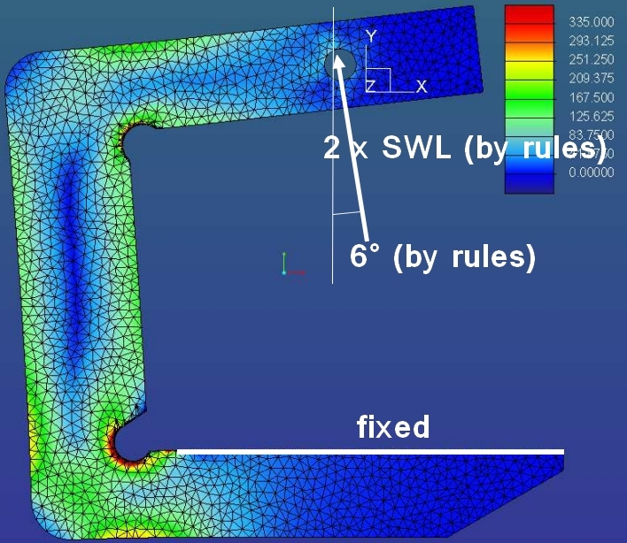
I tried to verify it using FEM method (PTC Simulate) and applying EN13155 rules: at 2xSWL + weight the maximum equivalent stress should be less then the yield strenght.

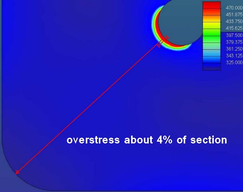
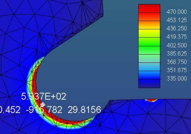
Well, my calculation says that the maximum stress is at about 600 MPa!!
So I tried to verify another certified hook, and the stresses are about the same. So, my doubt is: is the material not equivalent? Which materials are generally used in C-hook construction? S690 maybe?

TIA,
Max

attach: tensions over blue are over yield strenght (335 depending by thickness).

1_bizd3x.jpg
 
Replies continue below

Recommended for you

Does the "EN13155 rules" specify the use of FEM and also specify exactly what the load assumptions are (where on the hook the load is supported)?
There are analytical solutions for curved beams which would presumably give you different results, and moving the point of load application would give you different results.
 
Maxpcc:
So, what the heck is a C-hook for coil, I don’t need my coil hooked? Show a few sketches and FBD’s (free body diags.). I do think I know what you are talking about, but, you shut out about 80% of the population of potential posters when you don’t define your problem better, and use too many industry specific acronyms, etc.

You will always have high stresses in that region of the hook. That is why all C-hooks have a generous radius in that reentrant corner, or better yet, a protected (kinda hidden from field damage) high stress relief shaped reentrant corner, as you show in your FEM model printout. The FEM will always show very high stresses in that region. You don’t know how to model (mesh) the region finely enough, and the FEM just doesn’t know what to do with the relatively sharp change in shape and geometry. Actually, your printout doesn’t look too bad, the region of overstress is pretty small vs. the larger hook material volume, and it will just do a little yielding and redistribute those high stresses a bit to inner material in the hook. The best thing you can do is to increase the dia. of the circular shape in that corner. That will start to show a reduction in max. stress, but obviously there is a limit to how big this dia. can be. Then, the next best thing to do, since this stress reducer is already fairly well protected from day to day abuse, is to do a real good job of cleaning up the final shape by grinding, in the same direction as the stress flow, not across that flow, etc. Also, grind a generous radius on the edges in that region, rather than leaving them sharp corners. You want to minimize any stress raiser nicks from daily use or any cutting/ fab. notches in this region. Otherwise, the thinking goes..., that that small high stress area is well confined by the volume of material around it which is below the yield stress; and we have cleaned-up the edges and corners which might be crack starters; and we inspect this region regularly during usage.
 
Might be the time for book solution.... 'Advanced Mechanics of Materials' by Boresi, et. al. has some good crane hook solutions.
My old fifth edition also points toward Wang having a effective algorithm .....
WANG, C. C. (1985). A Unified Algorithm for Accurately Sizing Straight and Curved Beam Sections to Allowable Stress Limits. Presented at ASME Des. Eng. Div. Conf. and Exhibit on Mech. Vibration and Noise, Cincinnati, OH, Sept. 10-13, Paper 85-DET 102.

Google search of that led to this...
Hope that helps!

ZCP
 
Ok, I have other images:

Costraint and load conditions are here represented, and I'm quite sure that they are correct
My question is still the same: which material is usually used? S355, with this condition of stress, IMHO is not appropriate.

2_qfu2yv.jpg

3_tzkrwf.jpg
 
Why the rather deep reentrant corner at the bottom?
You could easily move it to the right by about the length of the radius, without compromising protection of the corner or obstructing the load.
 
I agree with you, kingnero, but remember that I'm calculating a built hook for maximum SWL, so I can't bring any modification to design or material.
My question is: an equivalent hook, made by other constructor, has similar SWL with a lesser thickness. So: am I wrong or the material si not the same? I know my material, but I dont' know which material used the other constructor. Maybe S690, and someone thaht knows this application can suggest me the typical material fo C-hooks.
 
Has the equivalent hook the same geometry at that location?
I would be interested in the FEM analysis of the same hook, but with a slightly different geometry at the reentrant corner.

I could accept a bit overstress, but I'm also very wary when it comes to lifting or hoisting equipment.

For this application, I'd also prefer a more ductile metal over a high-strength steel, even though this is a very broad statement you certainly will get the point I'm making.

Sorry, can't help you here any further...
 
Maxpcc:
I agree with Kingnero on the points that he made, namely that you want a tougher and ductile steel for these types of equipment; that lower relief corner can be moved out to about the same position as the one at the top and you will gain some strength because you haven’t cut so deeply into the primary cross section. I understand that you can’t redo the existing hook.

This is a geometry of the structure problem, and you can’t really work yourself out of it by increasing the steel strength. FEA will always show very high stresses in that reentrant corner region, whatever the steel strength. So, it is tough to pick a high enough yield strength to overcome this stress concentration. It is better to change the geometry, with a bigger radius at that relief circle, but not at the expense of cutting too far into the main cross section. One thing you can do to protect that reentrant corner, when you move it outward, is to put a wear shoe on top of the lower horiz. leg, where your second attachment seems to show a while bar. Make it soft, about 1-1.5" thick and let it overhang the thickness of the C-hook by 1" on each side. Shape the top to match your smaller coil i.d’s. You will likely improve the stress concentration a bit if you start your stress relief curve at the top of the horiz. leg, and make it an elliptical shape, with long axis vert., or a long smooth curve, approx. circular at the horiz. leg, but then fairing back into the vert. leg in a long “S” curve. Now that you have the hook modeled, try this with several diff. size shapes, and with several diff. steel strengths for each shape, and report your findings. Fy won’t make any diff.; and a larger, more gradual radius or shape will reduce the stress level a little. The situation just won’t go away, becuase you are yanking that high tension stress field around that tight corner, the gross structural geometry.

You have to be able to explain what we’ve been talking about here, irrespective of exactly what the FEA shows, and you have to be able to explain why that FEA modeling anomaly happens too. It should be a warning to exercise some caution, control and finesse in your design, but it should not control the design or your better engineering judgement. In analyzing the hook you are looking at, you have to use good engineering judgement and the (industry’s) years of experience in designing these things. The codes and stds. set some min. FoS’s, etc., then you can be more conservative if conditions warrant. Is the existing hook beat to hell or has it been well treated? Are they protecting that reentrant corner, do they often lift more than the hook rating, etc. Could they put the wear shoe on top of the horiz. leg of the C-hook. These types of considerations, not just the red color on the FEA printout should be part of your final report.
 
Status
Not open for further replies.
Back
Top