LearningAlways
Structural
I am rehashing weld details and this is something that I struggle to agree with.
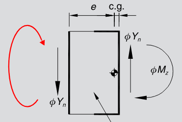
For a gap plate that has a c-shape weld on one side and a line weld on the other, the assumption is that one side is fixed and the other is pinned. Thus the c-shaped side takes into account load eccentricity from the line weld but that is not true from the line load perspective.
I don't see how the line load doesn't resist rotation and therefore doesn't undergo additional stresses. Despite the assumptions, the physical behavior suggests that both sides resist the eccentric loading.
I've attached a snip. I've accepted that this is the assumption but I don't agree with it. Can someone help reconcile the behavior and the assumption?

