Continue to Site

Eng-Tips is the largest engineering community on the Internet

Intelligent Work Forums for Engineering Professionals

  • Congratulations KootK on being selected by the Eng-Tips community for having the most helpful posts in the forums last week. Way to Go!

cable drawings

Miley223

Aerospace
Feb 21, 2023
3
So to me a cable drawing is when you have multiple wires bundles together.

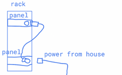
I have this flanged connector. So the house power cable is not long enough to reach our panel. so i have to build a cable that could get me from one panel to another panel on rack.
so i showed photo below. to build this cable i would have to attach the flanged connector to the panel first before i could attach the wires from connect to connector. These wires will be encompassed by a rubber sleeve.

i was going to create a cable drawing to show how this would all be built. i was going to have a note saying connector must be mounted on the panel first to build the harness.

I had someone mention this is a wiring diagram and not a harness since the connector has to be put on the panel first. definitely not the best design i will agree but it was a part we had on hand. would it be cable drawing or a wiring diagram?

to me a cable is a bundle of wires. a wiring diagram could represent a bunch of wires loose and not bundles together.

In addition, are there drawing standards for this. I did find much in the ASME standards on cable or wiring diagrams.
Screen Shot 2024-11-07 at 8.38.55 PM.png
 
Replies continue below

Recommended for you

Both.

A wiring diagram for a cable will typically include a wire list that includes the wire routing (from pin X on Connector A to pin Y on Connector B,) which are bundled together, lengths between junctions, and so forth. This is in parallel with the cable drawing that shows any orientation requirements and location of any cable markings. The panel is just a component of the cable and is shown on the cable drawing.
 
So to me a cable drawing is when you have multiple wires bundles together.

I have this flanged connector. So the house power cable is not long enough to reach our panel. so i have to build a cable that could get me from one panel to another panel on rack.
so i showed photo below. to build this cable i would have to attach the flanged connector to the panel first before i could attach the wires from connect to connector. These wires will be encompassed by a rubber sleeve.

i was going to create a cable drawing to show how this would all be built. i was going to have a note saying connector must be mounted on the panel first to build the harness.

I had someone mention this is a wiring diagram and not a harness since the connector has to be put on the panel first. definitely not the best design i will agree but it was a part we had on hand. would it be cable drawing or a wiring diagram?

to me a cable is a bundle of wires. a wiring diagram could represent a bunch of wires loose and not bundles together.

In addition, are there drawing standards for this. I did find much in the ASME standards on cable or wiring diagrams.
 
A wiring diagram is part of a cable drawing, as is the wire list which tells which wires are bundled into the cable and which pins or connections the wires are attached to and the parts list, which gives the exact part numbers for all the items that are part of the cable.

So, there is only a cable drawing to describe how to make a cable.

Per NASA:

6 CABLE HARNESS ASSEMBLY DRAWING REQUIREMENTS
A cable assembly drawing is prepared when the design activity has determined that a cable assembly is to be fabricated as a discrete item. This type of assembly drawing depicts an electrical cable assembly of defined length and establishes item identification for that assembly. The assembly consists of wires, shields, cables, or any combination of these, all insulated and with at least one branch properly terminated to connectors, terminal lugs, or other suitable devices (for example heaters, thermostats, pig-tail terminated sensors, jiffy-junctions, bus couplers) and is designed to be installed as a single unit for the interconnection of electrical or electronic equipment. The cable assembly drawing specifies all data required for the fabrication and test of a cable assembly to include potential information for installation at the next higher level. (for example, identification of pigtails)

See https://standards.nasa.gov/sites/default/files/standards/MSFC/Baseline/0/MSFC-STD-3631.pdf

A wiring diagram has no parts list and no individually identified wires and may tell nothing about which functions each wire performs.
 

Part and Inventory Search

Sponsor