Eng-Tips is the largest engineering community on the Internet

Intelligent Work Forums for Engineering Professionals

  • Congratulations waross on being selected by the Tek-Tips community for having the most helpful posts in the forums last week. Way to Go!

Calculate acceleration from an accelerometer

Status
Not open for further replies.

a_d

Geotechnical
Jun 30, 2022
8
0
0
NL
Hi,

I have an piezoelectric accelerometer that i am using for the pile test. It gives the output values in voltage.
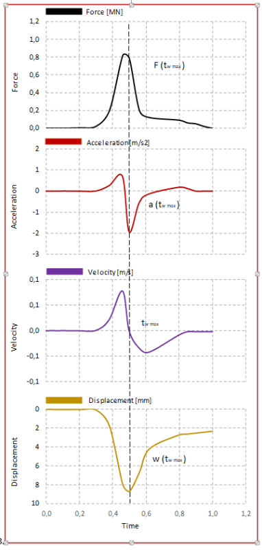
How can i convert the voltage into acceleration so that i can calculate the velocity and there by displacement of the pile head?
I have used the equation :
acceleration = voltage/sensitivity.
but if i use this equation, i am not getting the correct velocity and displacement graph.

Thank you in advance!
 
Replies continue below

Recommended for you

Acceleration = Force/mass

Perhaps it needs to be calibrated.


A black swan to a turkey is a white swan to the butcher ... and to Boeing.
 
Thank you for your reply.
the load is not free falling. it is mechanically done. and it is for a rapid load test.
i need to calculate the acceleration from the voltage measurements. the acceleration gives the output in volts, not in accelerations. It there are some issues with the load cell too. So i cannot calculate it from the Force. the only possibility is to calculate acceleration is from voltage.
Could you please help me?
 
Volts vs acceleration will be specific to your device. Output of a 3G accelerometer for a 5V circuit will be different from 10G accelerometers or those that might use a 4-20 mA current as an output signal.

I think you need a conversion chart from the makers of the device showing output voltage and the corresponding acceleration of the device, like the grey line in this one.
This may be typical of similar devices as yours, but I do not know.
A chart like this should be included in the tech info somewhere in the box, or contact the device mfgr.
V_output_vs_g_input_on6irg.gif


A black swan to a turkey is a white swan to the butcher ... and to Boeing.
 
Hope so. That's the only way I know to get acceleration from Volts.

A black swan to a turkey is a white swan to the butcher ... and to Boeing.
 
In the above chart, 0 g means the object is not moving? or the object is moving at constant velocity? What does actually the 0 g represents?
 
That it is not accelerating or decelerating. Its velocity vector remains constant. Moving at a constant speed in always the same direction, or completely at rest (velocity vector =0).

Einstein gave the same test to students every year. When asked why he would do something like that, "Because the answers had changed."
 
Thank you for your reply.
the chart that you have mentioned above is the relation of voltage with g. Is this relationship valid only if the acceleration in g's and voltage in volts?
or if the voltage is in mv or if the acceleration is in m/s2, how do i need to change it?
 
If i get the acceleration values(in g's) corresponding to the voltage values (from the manufacturer, like the one in the graph), do i need to do any other conversion? Like, conversion with the voltage value of zero g or something?

Or just the acceleration values corresponding to the measured voltage directly from the chart is the answer?
 
If you have the chart above for your device,
Start at voltage 4V
Draw horizontal line to the sloped line
Draw vertical line down to g = 1.6

That's acceleration in terms of number of earth gravity's.
g at the Earth's surface is 32.174 ft per second squared, so

Acceleration of the device in ft/sec^2 would be 1.6 g x 32.174 ft/sec^2 = 51.478 ft/sec^2


Einstein gave the same test to students every year. When asked why he would do something like that, "Because the answers had changed."
 
Thank you for your reply.
I checked it with the manufacturer. he says, there is no such thing for this accelerometer. i am unable to generate the acceleration values.
I need to calculate the velocity from the acceleration values and thereby displacement based on the below graph. It is for the Rapid load test.
[URL unfurl="true"]https://res.cloudinary.com/engineering-com/raw/upload/v1664887773/tips/Diagrams_1_h8ucdc.docx[/url]
And i am unable to generate an acceleration graph like the one in the attachement. Could you please help?
I have also attached a file with the values that i receive from the rapid load pile test. it is a for one blow.[URL unfurl="true"]https://res.cloudinary.com/engineering-com/raw/upload/v1664887975/tips/Paal-S06-19cm_zmut1w.xlsx[/url]
 
Capture1_ylgueq.png


What do the voltages represent on the Excel sheet?
Is each channel an acceleration direction on the x, y and z axes respectively?
I assume relative time is measures in seconds.

If you begin with an acceleration curve, the area below the curve between any two times is the change in velocity during that time. You can then construct the velocity curve. Likewise, the area below the velocity curve will be the change in distance moved.
If you know the mass of the object that the acceleramometer is attached to, the force curve can be calculated. F = mass * velocity.

I think you might be able to assume that your device has the same output voltage to acceleration as the graph I found. I would assume that it does and run some tests on an object of known mass to verify that assumption.

Einstein gave the same test to students every year. When asked why he would do something like that, "Because the answers had changed."
 
Thank you for your reply.
There are two columns that gives similar values in the excel sheet. Those are the volt values from the two accelerometers. we are using two accelerometers on the pile.
I have to get the proper acceleration values from those volt values. I am using the average of those two values. But i need to get positive and negative acceleration values. And i am not getting proper
acceleration values. And the velocity and displacement graphs results from the acceleration values. The voltage values are in the range of 0.2 v to 0.6 volt.
 
I've run out of ideas here.

As before, you might test the device in a known acceleration field to see what voltage reading you get under a known acceleration. I'm not sure how you would do that, but you have gravity, or maybe you can rig up a a rotating drum.

I have no idea what would happen if you glue them on a pile.


Einstein gave the same test to students every year. When asked why he would do something like that, "Because the answers had changed."
 
Status
Not open for further replies.
Back
Top