3 Ph, 415 V, 50 Hz 4 wire, neutral solidly earthed system feeding a high school with 3 phase ac's, LED & fluorescent lamps, ceiling fans, UPS systems for computers, lab equipments etc.
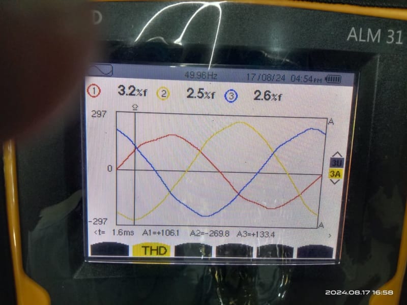
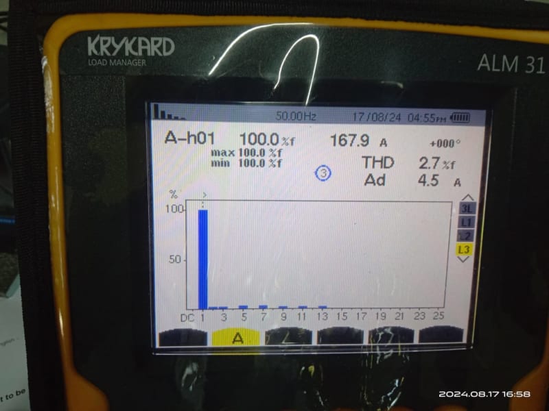
Current and voltage THD's in each phase <3%.
Current harmonics 3rd to 13th less than 0.5% in all 3 phases as per below photo
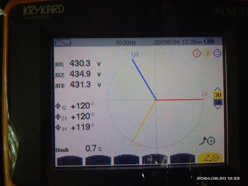
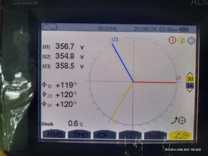
RY – 400 V YB – 401 V BR – 402 V
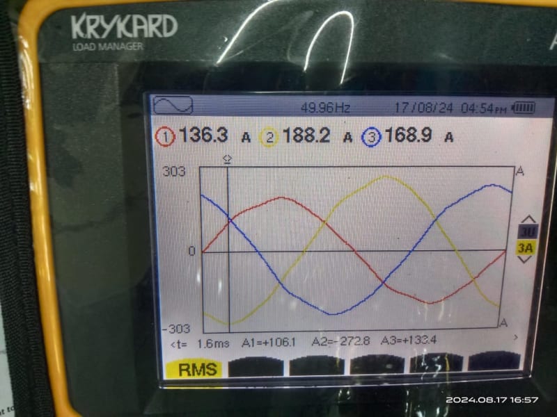
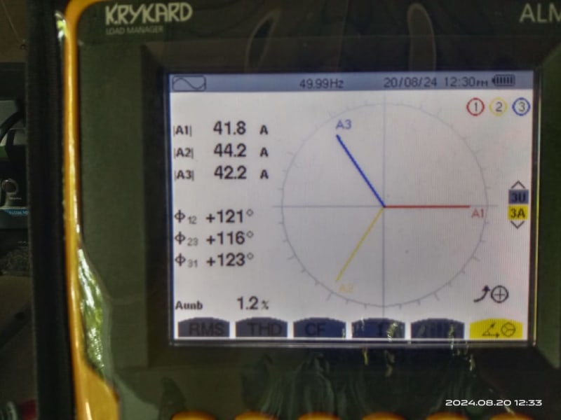
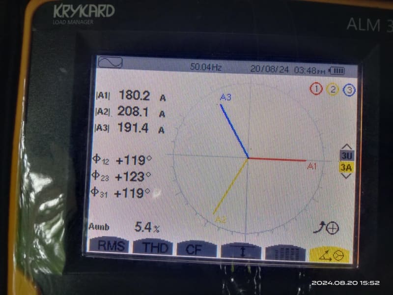
R – 135 A Y – 188 A B – 167 A
Using the formula, neutral current = Sqrt [(R^2 + Y^2 + B^2 – RY – YB – BR)], I get 46 A. (Online calculators also give 46 A neutral current).
But the measured neutral current is only 18 Amps.
Would appreciate any explanations.
Muthu
Current and voltage THD's in each phase <3%.
Current harmonics 3rd to 13th less than 0.5% in all 3 phases as per below photo
RY – 400 V YB – 401 V BR – 402 V
R – 135 A Y – 188 A B – 167 A
Using the formula, neutral current = Sqrt [(R^2 + Y^2 + B^2 – RY – YB – BR)], I get 46 A. (Online calculators also give 46 A neutral current).
But the measured neutral current is only 18 Amps.
Would appreciate any explanations.
Muthu