Continue to Site

Eng-Tips is the largest engineering community on the Internet

Intelligent Work Forums for Engineering Professionals

  • Congratulations KootK on being selected by the Eng-Tips community for having the most helpful posts in the forums last week. Way to Go!

Calculated neutral current not matching measured neutral current 4

Status
Not open for further replies.

edison123

Electrical
Oct 23, 2002
4,454
3 Ph, 415 V, 50 Hz 4 wire, neutral solidly earthed system feeding a high school with 3 phase ac's, LED & fluorescent lamps, ceiling fans, UPS systems for computers, lab equipments etc.

Current and voltage THD's in each phase <3%.

Current harmonics 3rd to 13th less than 0.5% in all 3 phases as per below photo

RY – 400 V YB – 401 V BR – 402 V

R – 135 A Y – 188 A B – 167 A

Using the formula, neutral current = Sqrt [(R^2 + Y^2 + B^2 – RY – YB – BR)], I get 46 A. (Online calculators also give 46 A neutral current).

But the measured neutral current is only 18 Amps.

Would appreciate any explanations.
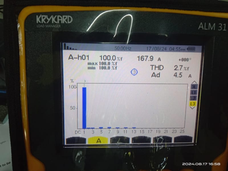
03_-_Harmonics_-_Current_B_egbq3q.jpg


Muthu
 
Replies continue below

Recommended for you

Neutral current at low load was 2 Amps

jghrist - The angles between the phasors A1, A2 and A3? How would you plug in these angles in your Excel sheet?

Muthu
 

For Full Load
Code:
Phase        Mag  	Angle deg	Angle Rad	Real	    Im
R	    180.2	    0	            0	        180.2	    0
Y	    208.1	  -119	         -2.08	       -100.89	  -182.01
B	    191.4	   119 	          2.08	        -92.79     167.40
N	    19.88			                -13.48     -14.61

Note that angles are only given to zero decimals. If the 119 angles were 118.5, then N would be 18.0 A.
 
edison123.
I have great respect for you.
It worries me that we cannot find a solution.
As you know, uneven voltages may cause disproportionate current differences.
Motors are noted for this.
The amount of difference depends on the motor impedance, the voltage difference compared to the back EMF and to the source impedance.
Your readings are typical of either single phase line to line loads or unequal currents caused by enequal supply voltages.
A suggestion;
If possible measure the neutral current of each line to neutral load on each phase and correlate that with your neutral current.
Turn off individual motor loads and check for any change in neutral current and check the change in line currents.
Beware that some three phase equipment may have internal line to line single phase loads such as heaters and or fans.
Respectfully yours
Bill

--------------------
Ohm's law
Not just a good idea;
It's the LAW!
 
Thanks jghrist . Your calculation tracks what I measured at neutral. If I may ask, how did you arrive at 0, 119, 119 angles ?

waross - Input voltages are pretty much equal. It's regulation that is the issue. I had the utility guy measure the voltages at their transformer end, which is about 600 ft away, from low load to full load. Transformer output stayed constant at 430 V. The issue is the too small overhead line from the transformer to our school. They will address it by increasing the line cs or stringing a second line. LED's and fans are single phase loads and are spread evenly in three phases as you can see at full load. At inevitable partial loads (service factor), there are bound to be unbalanced currents. Also, as you said, all 3 phase ac's have their outdoor unit fans connected to the same phase, which would create some unbalance. I am addressing the ac fans issue by shifting single phase loads from that phase to the other two phases. At the end of the day, we will have to live with some current unbalance, which is not a big deal.

Muthu
 
Also, as you said, all 3 phase ac's have their outdoor unit fans connected to the same phase, which would create some unbalance. I am addressing the ac fans issue by shifting single phase loads from that phase to the other two phases.
My point; Phase to phase unbalance does not create neutral current. Hence the incorrect results from the incomplete formula.

--------------------
Ohm's law
Not just a good idea;
It's the LAW!
 
I arbitrarily chose 0° for the R (A1) phase angle. The difference between R & Y phase angles is 119° per the meter (Phi 12), so Y phase angle is 0 - 119 = -119°. The difference between B & R phase angles is 119° (Phi 31), so B phase angle is 0 + 119 = 119°.
 
As long as you are looking at the difference of currents it should be OK, but, using an arbitrary base for the angle reference, if the arbitrary angle assignment crosses the base line so that the PF goes from negative to positive on one phase, will the calculations still work?
I don't know.
I am asking not challenging.

--------------------
Ohm's law
Not just a good idea;
It's the LAW!
 
If you use another phase for the 0°, you will get a different answer, but only because the angles are rounded to zero decimals. Note that the sum of all of the phase angle differences has to equal exactly 360°, but 119 + 119 + 123 = 361.
 
Status
Not open for further replies.

Part and Inventory Search

Sponsor