Eng-Tips is the largest engineering community on the Internet

Intelligent Work Forums for Engineering Professionals

Calculating additional Increase in Current due to Harmonics in the capacitor bank 2

Status
Not open for further replies.

adi 3291

Electrical
Mar 22, 2022
26
0
0
US
I am going through some of the NEPSI webinars and online resources, it was very helpful content on the harmonic filter and capacitor banks. Thank you for the resources.

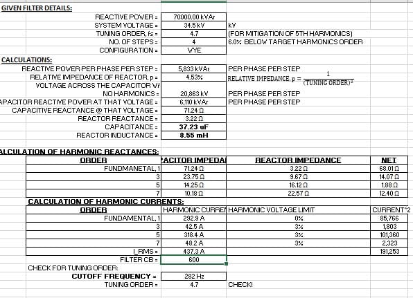
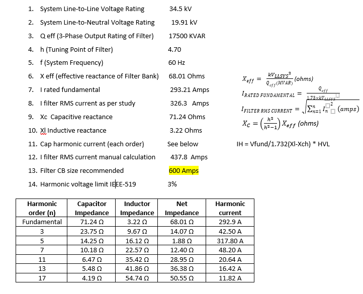
Our wind turbines experienced an abnormal amount of turbine faults and after investigating we identified that the faults were caused by high levels of harmonics while the capacitor banks were in service. After harmonic study analysis, identified resonant point at or near 5th harmonics and have high individual harmonic distortions at the 5th, 7th, and/or 11th harmonics. So sized and installed a single tuned bandpass filter tuned to the 5th harmonic on one of our capacitor banks. See attached for reference. Each capacitor bank is 17.5MVAR, rated @34.5KV and we have 4 of them on each bus.

After installing the filter also, we frequently saw blown fuses on capacitor banks. So what is the methodology to calculate an additional increase in current due to harmonics other than 5th in these capacitor banks, so we can size the fuses and disconnect switches correctly?

Each capacitor bank is 17.5MVAR, rated @34.5KV and we have 4 of them on each bus.
 
 https://files.engineering.com/getfile.aspx?folder=a1b3af04-dc53-42dd-89ab-df3101fccf64&file=Cap_bank_details.pdf
Replies continue below

Recommended for you

Each leg of the wye connected bank won't be rated for 34.5kV. I would bet money on that.

I have no idea how you came up with any of those other numbers. The reactor is listed as 8.55mH. The total capacitance is listed as 37.205uF. It's tuned to 282Hz or 4.55 harmonic.

It is confusing. The 1-line doesn't show a reactor on the other banks, with the resistor and inductor added to bank 1. The 3-line shows reactors on all banks and just the addition of a resistor on bank 1.
 
@LionelHutz (Electrical),
I am so sorry. I screwed up big time there! I didn't see the notes in the lower portion and failed to investigate the 2nd page of the attached document. Please disregard my last post.

 
Lagudu Aditya (Electrical)(OP)5 Jul 22 21:48
I think the fuses are blowing, as they been continuously running around 90% of their rating. It is causing a thermal stress. I want to know, how to manually calculate harmonic currents in the filter bank.
[li]I found out lately that the only mistake in the design of your filter is the sizing of the breaker, it's a bit smaller than if you apply a 125% fudge factor on the maximum Irms current that the filter will draw. My computations tell me your filter will draw a total of 437A! Please see below and check if I did it right[/li]
[li]The next trouble with my initial calculations is that I am constrained by thinking that the relative impedance of reactors is only available at a fixed % as per market availability (I tried using a relative impedance of 5%) instead of the actual relative impedance of 4.53% (tuning order = 4.7 =1/sqrt(relative impedance)! I was thinking these reactors (HV) are off-the-shelves![/li]
detune_filter_g6oc8o.jpg

I hope this provides closure to your problem.
 
@Parchie, Thank you for the calculation. I cross checked it, and the values are accurate.
Capture_qhn1nu.png


What is the significance of relative impedance and fudge factor?

We also want to upgrade the protection to a CB from the existing 400A fuse, but that is not an economical option for us at this time. I couldn't find any 35kV fuses bigger than 400A, are you aware of any bigger fuses than 400A?
 
@Lagudu Aditya (Electrical),
What I was computing was protecting the filter unit using circuit breakers.
On the fudge factor, NEC 460.8 requires 135% of the rated capacitor current for the capacitor conductors. Other references explained that 135% is applied for grounded wye cap banks and 125% should be applied to ungrounded units (filter duty).
In 460.8(B), it says the overcurrent protection shall be as low as possible, no factor is applied to the ampacity of the conductors, which is 135% of the expected capacitor current. IDK what type of fuse you are using. A material I've read from Cooper tells about dividing the resulting conductor ampacity by 1.5 when using NEMA type T or K fuses or a fudge factor of 0.9 from the computed capacitor current rating, 1.35/1.5=0.90. Since this is a filter, that fudge factor could go down to 1.25/1.5 =0.83! Please investigate if that is your actual fuse used. Perhaps that was what the designers intended to happen: using a NEMA type T or K fuse. Using a different type of fuse will result in unwanted fuse blowing.
Here:
Fuse link amps = 1.25/1.5 x 437.3 = 363A, hence, a 400A fuse, NEMA type T or K!
On the relative impedance thing, it is another way of expressing the tuning order like the way you computed. You can also use the target cutoff frequency in computing the element values. Tuning order = sqrt(1/relative impedance).
 
Aditya,

to me the recent calculation seem to be correct (beside the fact that the fundamental voltage at the capacitors will be higher as the incoming voltage due to the inductor - line 7).

So, the 400 A fuse just does its job when it trips at 437.8 A.

But what study led to the RMS value of 326.3 A (line 8) ? This might be valid for an untuned bank, but for sure not for the filter design.
 
@ electricuwe (Electrical)

Thank you for the cross check.

Line 8 item was a rough estimate and it is for cap bank only. And we didn't perform post installation harmonic study, this estimate is before installation of filter bank.
 
You can parallel fuses.

The bank is a 5th harmonic trap now, so whatever 5th harmonics are present will mostly get trapped by it. No-one can know the level unless it's measured.
 
@Parchie (Electrical)
As mentioned by our current fuse manufacturer, the existing fuses when subjected to continuous currents at or around 85-100% of the element melt rating do get warm. It wouldn’t take much of a current surge at 85% to blow it. Potentially a surge when switching your cap bank on.

We are using NEMA Fuse Element Type N and these are superseded by Type K and T links. As in the case of NEMA type T and K tin links, they can carry 150% of rated current continuously. Silver T and K links can carry 100% of rated current continuously. May be changing the fuse element to Type K and T could be a viable option for us.

And for the filter bank when the total RMS current with harmonics is coming as 437Amps, why do we consider a 400A fuse, it should be something higher than 437A right?


@Lagudu Aditya,
The RMS current draw is what the fuses respond to as this will cause heat to "melt" the fuse links. Manufacturers release data on the time-current characteristics of their products and there, you will see at what current will their fuse links clear the fault.
For a type K fuse e.g., 200K will clear at around 10 minutes for a current of 579A. That's about 290%! We can deduce that fuses will not melt or clear at a certain percentage above their published ratings. Like the fuse manufacturer's claims, type T or K fuses are sure to carry 150% continuously. If the actual current is 437A OR 400*1.5/437 = 137%, that is well below the maximum of 150% (600A)--> if the fuses were of the type T or K, that is.
 
I have to disagree to Parchie on using fuses above their rated current. For a good insight into MV fuse technology look here:


MV harmonic filtering is really a challenging topic. When we had a deeper look into the topic about 20 years ago. We discarded that option and decided to address the topic at the source by applying a more advanced converter topology.

The company that consulted us at that time, MR Reinhausen, now has an active filter solution in its portfolio as passive solutions are complex and have many limitations.
 
@electricuwe,
Please read page 3 of the attached document from Eaton.
link
It's there, type T-silver and type K-tin allowable continuous current (% of rating) is 150%." I'm not making things up.
 
Parchie (Electrical)

At 35kV voltage level, even Eaton doesn't have bigger than 100A fuse links, which won't be helpful anyway in this situation.
 
Parchie,

but the document also states:

"Additional continuous current-carrying capacity is particularly useful in applications where coordination requires greater load-carrying
ability for specific time periods."

Hence not suitable for continious operation over longer periods.
 
@electricuwe,
IDK how you see it that way. My take on the article section you pointed out is that the 50% additional current capacity brought about by the fuse characteristic at loads above the rated nameplate will allow for better coordination with other protections, which is true because the type T and type K fuses will not clear until 150% of its rating. It did not say "not good for continuous operations. I guess you focused on the phrase "specific periods", which means those periods where better coordination of the protection devices are needed during faults and faults are very short.
 
@Lagudu Aditya,
As mentioned by @ Lionel, there are parallel-connected fuses. But the code prohibits us from doing the field conversion as the code says that is only allowed if "factory assembled". I recommend that your company ask your fuse manufacturer of choice about making them for you. Perhaps this is a result of a review by the CMP regarding the risks involved and how to provide a walkaround with these problems, making safe products that are properly tested and verified.
Please try and compare the costs of buying capacitor switches (vacuum switches) versus buying special fuses (if companies do make them nowadays).
 
@Parchie,

Thanks for the comments on parallel fusing. For reference, we do have cap switchers on individual banks, that operates only during voltage unbalance conditions, that takes the signal from the relay. We only have PT in the, no CTs were installed before in the cap bank/filter bank circuit.
 
Status
Not open for further replies.
Back
Top