Continue to Site

Eng-Tips is the largest engineering community on the Internet

Intelligent Work Forums for Engineering Professionals

  • Congratulations KootK on being selected by the Eng-Tips community for having the most helpful posts in the forums last week. Way to Go!

Calculating Axial Load in a Tire Beam

Tygra_1983

Student
Oct 8, 2021
121
Hi,

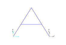
I have the following example where by I am trying to calculate the axial force in the tie beam:
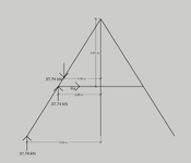
Screenshot 2024-11-25 190100.png
The geometry is: width = 10m, height = 8 metres, angle = 57.995 degrees. The diagonal members are 9.43m (sqrt(89))


And these are the support reactions:
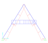
Screenshot 2024-11-25 190714.png

If the tie beam is fully fixed I can take moments about the apex and calculate the axial force of the tie beam member. However, this does not work out with the tie beam being pinned.

In my attempt to solve this I calculate the moment in the joint that connects the tie beam to the main frame, and add that into the equation taking moments about the apex.

The moment at the joint in this example is 63.04 kNm. The pinned connection has both horizontal and vertical components. Hence:


1732562224943.png


Solving for Ax, gives 30.4 kN

In the software I am getting 28.5 kN. So close, but not completely correct.

Am I going about this the right way?

Thank you in advance!
 

Attachments

  • 1732562155780.png
    1732562155780.png
    13.7 KB · Views: 2
  • 1732562174462.png
    1732562174462.png
    13.4 KB · Views: 2
Replies continue below

Recommended for you

You need to explain your long equation, and you need to identify the height of the tie bar from the ground. Taking moments about the apex seems like the right approach. Specifically the first two terms should be of opposite sign I think if they mean what I think they mean.
 
Hi Greg,

Hopefully, this diagram will clear some things up.

Screenshot 2024-11-25 230112.png

The long equation is the moments taken about the apex.

Sorry I see now, I made a couple of typos to the original equation. I am assuming anti-clockwise as positive about the apex, so yes, the first two terms are negative, but end up being positive after making Ax the subject.

1732576333054.png


1732576421991.png
 

Attachments

  • 1732576001401.png
    1732576001401.png
    21.6 KB · Views: 1
  • 1732576105025.png
    1732576105025.png
    26 KB · Views: 1
  • 1732576221494.png
    1732576221494.png
    17.5 KB · Views: 1
  • 1732576245071.png
    1732576245071.png
    18.2 KB · Views: 1
Last edited:
I have a suggestion regarding your long calculation that also applies to every calculation that you perform: please attach units to each number that needs one.
 
Where on earth is the upwards 37.74 coming from? How come you've changed the sign of one part of the equation and still get the same answer?
 
are the sloping members (the roof) pinned at the apex ? or is the moment capability there ??

I don't "think" your approach is correct, as I see this as a redundant structure. So how would the sloping members deform if the tie beam wasn't there ?

Random thought ... the tie beam is fixed at both ends, but unloaded, so therefore is under constant moment ?
No, that's not right ... there should be zero moment on the plane of symmetry ?
Hmmm, could the tie beam react the peak moment ?
The tie beam would have load in it even if it were pinned ends ... the two fixed ends react one another ...
 
I assumed the top was a pin joint in which case I get 37.74*(5-2.5)/4.61, which is nowhere near any of the other answers, ignoring the upward force on the tie beam. Where does 63.04 come from? why is there an upward force at the tie beam?
 
37.7 is (I guess) the load on one roof ... and reacted at the ground from overall FBD. But then look at 1 side only ... there is a couple between the load and the ground reaction, which could be a moment on the tie beam, or a horizontal couple between the tie beam and the peak, or both. Both (most likely to my mind) makes the problem redundant, so how does the roof deflect at the tie beam attachment point (without a tie beam) ? Now (without a tie beam) I think you need a horizontal couple between the ground and the peak.
 
Sorry, here is the equation with units:

1732618287259.png


To clarify, the main diagonal structure is fixed at the apex. The tie beam is pinned. Also, because of symmetry I am only considering one side in the calculation. The load on the frame is 4kN/m.

The upwards force is the vertical reaction at the pin of the tie beam.

The moment of 63.04 kNm is the moment at the joint where the tie beam connects to the main diagonal frame.

This is calculated by:

1732619341766.png

Theta = 57.99 deg and where x = 4m (distance from support to joint intersection) gives at moment of 63.04 kNm.

Like I said before if the tie beam is fixed to the main frame I can take moments about the apex and find the axial force in the tie beam (anti-clockwise as positive)

1732619612255.png

1732619033479.png

The model in SAP2000 gives 21.19 kN. So we are basically there.

So, the question is: what do you do differently if the tie beam is pinned under the same loading? Being pinned the axial force increases. The answer from the software is 28.5 kN. My calculations has given me an axial force of 30.4 kN.
 

Attachments

  • 1732617915469.png
    1732617915469.png
    15.8 KB · Views: 0
  • 1732617940568.png
    1732617940568.png
    10.6 KB · Views: 0
Last edited:
what is 37.4*2.88 ? why have the tie beam reacting the load in shear ? check your FBD !

your M equation is some sort of standard reference ? Does this equation work with a tie beam ? Probably, 'caue in the absence of a tie beam the peak moment is easy to calculate = 37.74*(5-2.5) = 94.35 kNm. Though I am surprised there is a handy moment calc, since the moment depends on the tie beam load ?

why say "To clarify, ... The tie beam is pinned." and then say "The tie beam is pinned." ?? which is it ? which is compatible with your M equation, since I think it'll change depending on the fixity of the tie beam.

Under this load the roof will deflect "inwards", putting the tie beam in compression. The tie beam load is balanced by a lateral load at the peak, creating a couple, reducing the peak moment. If the peak moment (with the tie beam) is your 63.04 kNm, then the tie beam load is (94.35-63.04)/4.608 = 6.79 kN.

Whatever you calculate, redraw your FBD of the 1/2 roof to check ... but the trouble with redundant structures is that they can lie ! The calculation can be circular and not correct (like above ... "assuming" the peak moment is 63.04 then the tie force is 6.79, but if the tie force is 21.19 then the moment (at the peak) is -3.29 ... both these solutions should produce a balancing FBD but one or both are "wrong" !?).
 
If the main frame is moment-fixed at the apex, the problem is indeterminate, and the force in the tie beam will be a function of the relative stiffness of the main frame members and the tie beam.

Think about it, if you remove the tie beam (i.e. zero force in the tie beam), the frame will still stand up, but it will tend to spread. If you use a substantial steel cable or piece of pipe, you will reduce the amount of spreading, and there will be a substantial force in the tie beam.
 
I'm going to hazard a guess that this is a timber roof truss, and the apex in that case is usually treated as pinned. Any rotational stiffness in the joint is then a bonus.
 
Last edited:
without the tie beam, and with a pinned peak (I agree a natural assumption) then there is a lateral couple between the ground and the peak, to balance the couple between the vertical load and ground. This is a three force member, with a horizontal reaction at the peak, a vertical load at the mid-point of the roof and the ground reaction inclined to pass through the intersection of these two forces.

Now you could put a rafter between the ground points of the roof,, and it would carry one lateral load to the other, and leave vertical ground reactions (as the good builder intended ... walls are good for vertical in-plane loads.

The point of the tie beam is to reduce the lateral reactions at the ground (what jhardy means by "will tend to spread"). With that logic (and assuming the tie beam is pinned to the roof) the tie beam load is 37.74*2.5/4.608 = 20.475 kN. This is for a pinned tie beam. If fixed, then redundant (and I haven't got time to solve that) but I would be surprised that the redundancy is increasing the load in the tie beam. I don't know where my answer fits with yours ... why the difference, no doubt in the detail assumptions.

can you show this "x = 4m (distance from support to joint intersection)" on the sketch ? I don't see where it fits ??
 
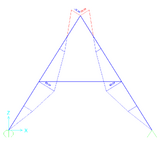
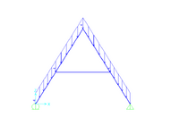
Here are the axial forces from thew SAP2000 model

Screenshot 2024-11-27 112513.png
Here, are the bending moments.

Screenshot 2024-11-27 112952.png
EDIT: I have gone for the apex being pinned, and from this I get the answer I was looking for. I have been following a book with a similar example and I thought the apex was fixed.

rb1957, you answer of 20.47 kN was correct.

Sorry to have wasted your time.
 
Last edited:

Part and Inventory Search

Sponsor