Continue to Site

Eng-Tips is the largest engineering community on the Internet

Intelligent Work Forums for Engineering Professionals

  • Congratulations GregLocock on being selected by the Eng-Tips community for having the most helpful posts in the forums last week. Way to Go!

Calculating oil pressure increase in a cylinder when force is applied

Status
Not open for further replies.

Jbingham1981

Industrial
Dec 6, 2018
3
Hi.. 1st time posting here and not an engineer by trade so I appreciate any help/guidance and will do my best to be clear.

I have designed a small water rotational swivel. It is essentially a housing with a shaft through it. The shaft has 2 radial bearings on it. The housing is sealed on both ends. The inlet side of the swivel is larger than the outlet side on the OD of the shaft.

I intend to have the housing filled with hydraulic oil (type not yet determined) prior to being sealed.

During operation, the shaft inside will move forward because of the force of the water, with the smaller OD exiting the housing seal and more of the larger inlet side entering the housing. This should increase oil pressure, acting like a piston compressing the oil. Maybe I'm wrong about that?

My questions are these:

Is there a specific formula to calculate the oil pressure if the increase in shaft volume and oil type/weight/viscosity is known? I'd like to know that if I allow X amount of movement of the shaft (allowing a specific amount of shaft volume to enter the housing) it will correspond to ?? Oil pressure increase.

Am I correct in assuming that if I can increase the oil pressure inside of the housing to a force greater than the axial thrust forward on the shaft from the water, I will create some form of hydrodynamic bearing? Will the thrust of the water and the oil pressure find a "neutral" position at any point, eliminating axial thrust?

Any help on this is greatly appreciated.
 
Replies continue below

Recommended for you

This needs a drawing, or sketch as it's too difficult to work out from a written description.

But from what I can gather if your internal sealed oil volume is decreasing the increase in pressure you can calculate using the Bulk Modulus of your oil assuming you have 100% oil in the void.

It won't take much of a volume change to get a huge pressure change.

Mineral oil is about 2.5 x 10^5 psi BM. in other words to get say a pressure increase of 1000 psi your volume would only need to change by 1000 / 2.5 10^5 = 0.4%

This assumes your housing doesn't expand, which is quite a big assumption. Any air or gas in the housing will change things hugely.

yes forces will eventually balance but depends on the amount of volume change.

Remember - More details = better answers
Also: If you get a response it's polite to respond to it.
 
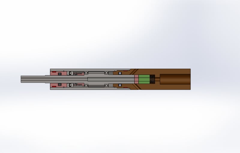
Hi. Thanks for the basic information. I've attached a section view of the model as it sits now.

The water will enter through the brown adapter on the right hand side. It should generate no more than 400 lbs of axial thrust on the shaft/disc/seal combo. The radial bearings are a slip fit to be able to move when presented with an axial load. The hope of the design is that the increased area of the inlet side of the shaft moving in to the housing due to water thrust will increase internal oil pressure due to increased volume in the housing. Again, am hoping that the oil pressure will reach or find "neutral" around 400 PSI internally and will allow this device to swivel with quite a bit less friction than it would with no oil pressure.

The left side of the shaft (longest journal) is approximately .188" OD while the right side journal is approx .218" OD, so .030" larger. The shaft is designed to move forward due to thrust a maximum of .125"

13mm_OD_Pipe_Tool_V2_oqdbef.jpg
 
Is there a specific formula to calculate the oil pressure if the increase in shaft volume and oil type/weight/viscosity is known? I'd like to know that if I allow X amount of movement of the shaft (allowing a specific amount of shaft volume to enter the housing) it will correspond to ?? Oil pressure increase.
Yes, there is an equation.
The basic equation is
Code:
ΔP = β*ΔV/V+P0
Where:
ΔP is the change in pressure
β is the bulk modulus of oil
ΔV is the volume the oil is compress
V is the volume of oil under compression
P0 is the initial pressure.

This simple formula doesn't address how far the shaft will move because it will see an opposing force and be not move as far as you think.
A good model for this would assume that a force is applied to the shaft. The shaft starts to move compressing the oil. As the oil pressure increase it opposes the force that is being applied to the shaft. Eventually an equilibrium of forces will be found and there will be no motion but before that the shaft may go a little beyond the equilibrium state. The simple equation above does not compute ΔV.
So what is the nature of the force on the shaft?


Peter Nachtwey
Delta Computer Systems
 
The delta V will be the product of the area difference between the two shaft cross sections multiplied by the delta shaft movment.

Ted
 
The delta V will be the product of the area difference between the two shaft cross sections multiplied by the delta shaft movment.
But how far will the shaft movement be? That depends on the force and opposing force. The shaft will move until there is an equilibrium. This is why we need to know about the force that is moving the shaft. You can see that there is also a P0 or initial pressure term.

Peter Nachtwey
Delta Computer Systems
 
Thanks to everyone that has chimed in. I really appreciate the feedback and help.

The pressure on that shaft driving forward should be approximately 400 lbs of axial load, caused by the high pressure water hitting the exposed area of the shaft/seal. 40,000 PSI of water pressure and an exposed area of 0.01sq2

The problem we're really faced with is that this design is very, very small... 13MM OD on the housing. The thrust bearing is only rated to around 215 lbs of force and due to size constraints, there's nothing else available that will allow for more axial load.

The hope is to offset some of the axial load of the shaft by creating a hydrodynamic bearing effect in conjunction with the trust bearing in the oil housing chamber due to increased oil volume.

Sounds like we're on the right track and will continue to monitor.

If anyone has additional feedback, it is greatly appreciated!

 
The important part of hydrodynamic is dynamic. How fast will the bearing surfaces be moving in order to create the hydrodynamic fluid bearing support?

Make space for a thrust bearing.

Ted
 
The important part of hydrodynamic is dynamic. How fast will the bearing surfaces be moving in order to create the hydrodynamic fluid bearing support?
To calculate the forces/pressure/position as a function of time requires differential equations and we have already established that few even understand Laplace transforms.

I think the hydraulic community better get its game face on because the servo motor bullies will beat you down and take your lunch money.


Peter Nachtwey
Delta Computer Systems
 
I will bet that most PD and PID input paramaters are solved thru experimenting with the the system and inputing values in the program to find the sweet spots. I know that this how it is done with bleed down valves on aircraft test stands. The paramaters and variables for inputs to the Laplace transform are generally not available or take forever to find. Using the program to zero in on the correct feedback paramters PD or PID should Usually be quicker.

The field Engineers for stablizng systems of ships also do alot of "Tweeking" with thier variables on sea Trials that I have been on. I do not know if thier initial inputs where based on laplace transform or empirical data.

In more complicated systems it may be worth while. And that once a experiment is done the paramaters could be defined and then used to predict similiar systems, which would be more efficient.
 
I will bet that most PD and PID input paramaters are solved thru experimenting with the the system and inputing values in the program to find the sweet spots.
This is certainly the way it has been done in the past. There is no need to do it that way now.

The paramaters and variables for inputs to the Laplace transform are generally not available
Well why not? This is one of my biggest complaints about so called hydraulic or mechanical "designers". If the designers can't stamp a transfer function on the machine are they really designing anything?

or take forever to find
Again, this is the way it was in the past. Not any more. The open loop gain, natural frequency and damping can be found in a minute.

Using the program to zero in on the correct feedback paramters PD or PID should Usually be quicker.
Yes, it is very quick now. A minute or two is all it takes if the system is designed well.

The field Engineers for stablizng systems of ships also do alot of "Tweeking" with thier variables on sea Trials that I have been on. I do not know if thier initial inputs where based on laplace transform or empirical data.
This is sad. The field engineers didn't 'design' the system yet they are the ones that are expected to make it work. I have NEVER seen a hydraulic servo system with a documented model.

In more complicated systems it may be worth while.
Even simple systems. I have been flown to plants where I must tune 64 actuators. If the system was designed right it takes only about a minute or two to tune one actuator. Tuning four actuators that are connected will take much longer.

And that once a experiment is done the paramaters could be defined and then used to predict similiar systems, which would be more efficient.
Yes, usually once one actuator is working, any similar actuators will be easy to get going by just copying and pasting parameter but these will still require fine tuning.
What is even better is that the parameters can be saved and used on the next similar project and even be used to simulate the system so the programming and sequencing can be 95% done before going into the field.


Peter Nachtwey
Delta Computer Systems
 
Status
Not open for further replies.

Part and Inventory Search

Sponsor