Eng-Tips is the largest engineering community on the Internet

Intelligent Work Forums for Engineering Professionals

  • Congratulations waross on being selected by the Tek-Tips community for having the most helpful posts in the forums last week. Way to Go!

Calculating Settlement of Fill Embankment Shoulder Widening

Status
Not open for further replies.

Mad Mike

Geotechnical
Sep 26, 2016
220
0
0
ZA
Hi All,

I've just commenced the geotechnical investigations for a highway widening which seeks to add an additional carriageway to our existing highway.

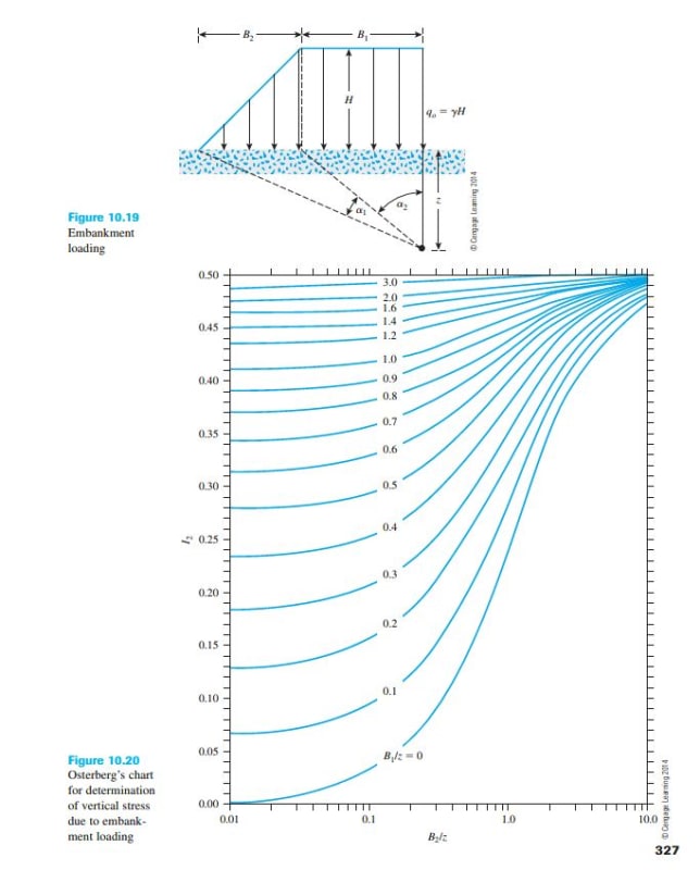
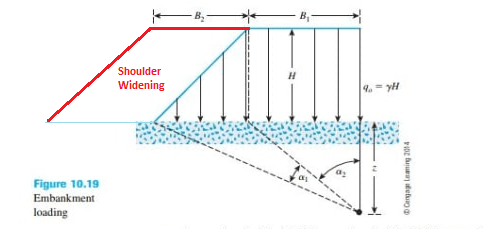
There are some substantial fills (10 - 20m high) along the route, mostly coinciding with drainage structures (large culverts) beneath, and I need to calculate the anticipated settlements beneath the proposed fill widening. Both the existing and the proposed widening are sloped at 1:2 (V:H).

I am unsure how to calculate the settlements with a fill shoulder widening- I'm currently trying to configure the profile on Settle3D (Rocscience) but I'm struggling. I would also like to know how to calculate the earth pressures by hand. There are a number of cases where differential settlement between the existing culverts and the proposed culvert extensions will be difficult to design for, so I want to be as accurate as possible.

Any guidance or references would be greatly appreciated.

Best,
Mike

 
Replies continue below

Recommended for you

Numerical grid and mesh modelling with rocscience or geostudio should be considered to determine the settlement values in critical areas. Obviously the result will depend on the range of expected behavior of the subsoil, elastic deformation on dense sand deposits you can expect very little, where as slightly over consolidated clay would have significant deformations if the load has exceeded the preconsolidation pressure and your into the normally consolidated range of settlements.
 
Thanks GeoEnvGuy - I don't have access to finite modelling software, so will be jumping between Settle3D and hand calculations.

In general, the drainage lines contain a few metres of loose to medium dense sand. We have very little clay, so long term remoulding is not something I'm worried about- my concern is with the immediate settlements as they build up the high fills over the culvert extensions.

Thanks for taking the time to respond.

Mike
 
Mike,

I agree that a 2D/3D FEM would be the most accurate solution but unfortunately you done have that luxury. But SETTLE 3D should also work?

Das - Principals of Geotechnical Engineering, has a section on embankment loading. The only difference between settlement calculations beneath an embankment is that you will have a variable stress beneath the sloped portion.

You should be able to use the below to assess the magnitude of stress, then settlement across the across the pipe?

Capture_c0jeqf.jpg
 
EireChch,

Thank you for the detailed and informative response. See my sketch below - I'm comfortable calculating settlements beneath a new fill embankment, but in my case we are doing a widening of variable width on the shoulder of an old fill embankment. In some cases the widening will be a thin sliver, but in other cases it will be very wide.

Significantly different to your sketch though, is the fact that my fill embankments- both the old embankment shown by your blue line and the new embankment shown by my red lines- are sloped at 1:2 (V:H), so because they're much flatter, there are many cases where the final widened road shoulder does not extend to beyond the original fill embankment toe point.

The settlements beneath an extremely narrow shoulder widening would be effectively zero (for a nominal sliver of new fill benched into existing) but then obviously, as the shoulder widening increases, the amount of stress on the natural ground at the toe of the widening gradually increases, until effectively we are creating a new embankment. In this last case, I simply model a full new embankment and calculate settlement from that, but in the intermediate stages of widening (say widening by only 3m, 5m or 10m) I don't know what pressure to apply to the in-situ ground beneath the widened embankment.

I suppose I should explain that the variable extent of the widening is because some of the widening was planned for- the fills were therefore constructed fairly wide during the original highway project, more than 20 years ago, but there was not enough material to accommodate the width of carriageway that we are now looking at.

Shoulder_widening_sketch_g78bts.png
 
MadMike - I do not know what kind of material onto which you are building. This, as you are fully aware, determines the "magnitude" of problems - if on glacial till; likely not much of an issue, if on soft clay or peat it will be a huge issue.

What I would suggest is that you get Poulos and Davis' book Elastic Solutions for Soil and Rock Mechanics. You can find it on the internet with a little digging. You then would look at the situation using elastic "construction". Put on your existing cross section profile. What has it done to the original compressibility of the existing ground - of course, there will be effects beyond the toe of the embankment. Knowing "pre" properties and then "post" properties - you can see what the compressibility characteristic is especially on the slope of the embankment and beyond. Then on your new widening. Determine the stress increase at the base and along the embankment slope - add the vertical stresses to the vertical stresses of the old embankment. Then with luck you can see what the additional stresses will do the compressibility of the grade both under the existing embankment slope and under the new widening (beyond the existing embankment toe). I'm in a hurry to get to a meeting so I hope that this was somewhat clear . ..

I was involved with a job in Surrey BC widening - came on late in the construction and they had taken out the peat and then replaced it with good granular fill. Of course, there ended up being a longitudinal crack between the new and old. Fallacy was removing the very compressible peat - overlying soft to firm clay, but replacing the peat with "dense" fill causing settlement in the underlying clay which then settled. Never got into a detailed analysis of this way back when.

 
BigH - your response is a huge help, so my sincere thanks for it and for the references. Your description paints a good picture of how I should go about analyzing it.

My geology is as good as it could possibly get...the bedrock is weathered granite and so the transported alluvial soils are generally inorganic sands, gravel and boulders, coarse and well graded but loose. So there will be a significant amount of immediate settlement as the new fill is built up. Placed directly over the concrete structures, this could be problematic.

If my analyses show valley crossings where the settlement is excessive, I will suggest a preload before the structures are installed...it will be at least a 2 year construction contract, so plenty of time to address it.

Have a great weekend!
Mike
 
The big problem with Settle 3D is that the effective stress is AVERAGED over the entire width of the layer; it is a grossly inaccurate calculation of the effective stresses beneath the embankment. It’s use of finite elements is wasted.
 
Status
Not open for further replies.
Back
Top