KristianSilva
Mechanical
- Feb 6, 2020
- 3
Hi,
I'm working on a material handling design and in the process of sizing a trapezoidal lead screw that has twin left and right threads (is there a formal name for this arrangement??).
The twin lead screw performs a similar function to that seen in a self-centring vice ( i.e, it is being used to self-centre and clamp a work piece.

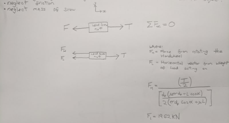
To size an appropriate lead screw, I am calculating the total tension in the lead screw which will be the 2x the force F (see diagram), plus the additional tension produced when a torque is applied to the hand-wheel. To calculate the tension produced when a torque is applied to the hand-wheel I have used the below equation taken from Mechanical Design Engineering Handbook pp697 by Peter R.N. Childs:

Where:
T = torque
P = load/tension
dp = pitch dia
L = thread lead
alpha = thread angle
I understand this method would be accurate for single/ordinary lead screw, e.g., considering a jack or one half of the twin lead screw in this application, however I am unsure how the addition of an opposing thread will effect the tension produced when a torque is applied to the hand-wheel?
Looking at the application and deriving the equation I am thinking that I need to double the thread lead used in this equation as this governs the thread lead angle which has now effectively doubled, doubling the inclination angle of the plane which the load acts on, however I am uncertain and would welcome some guidance.
Hope this makes sense, let me know if it doesn't!
Kristian
I'm working on a material handling design and in the process of sizing a trapezoidal lead screw that has twin left and right threads (is there a formal name for this arrangement??).
The twin lead screw performs a similar function to that seen in a self-centring vice ( i.e, it is being used to self-centre and clamp a work piece.

To size an appropriate lead screw, I am calculating the total tension in the lead screw which will be the 2x the force F (see diagram), plus the additional tension produced when a torque is applied to the hand-wheel. To calculate the tension produced when a torque is applied to the hand-wheel I have used the below equation taken from Mechanical Design Engineering Handbook pp697 by Peter R.N. Childs:

Where:
T = torque
P = load/tension
dp = pitch dia
L = thread lead
alpha = thread angle
I understand this method would be accurate for single/ordinary lead screw, e.g., considering a jack or one half of the twin lead screw in this application, however I am unsure how the addition of an opposing thread will effect the tension produced when a torque is applied to the hand-wheel?
Looking at the application and deriving the equation I am thinking that I need to double the thread lead used in this equation as this governs the thread lead angle which has now effectively doubled, doubling the inclination angle of the plane which the load acts on, however I am uncertain and would welcome some guidance.
Hope this makes sense, let me know if it doesn't!
Kristian

