Eng-Tips is the largest engineering community on the Internet

Intelligent Work Forums for Engineering Professionals

Calculating the the tank fill rate of an automatic fill valve. 2

Status
Not open for further replies.

SprinklerDesigner2

Mechanical
Nov 30, 2006
1,243
0
36
US
In 45 years I have yet to have a project where I would have to have a ground storage tank because where I am, south Georgia swamp land, I've always gone with a vertical turbine pump out of a pond. Travis, where I am if you did a hole it will fill with water.

I have a storage facility that requires 1,704 gpm for 60 minutes.

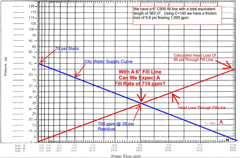
City water supply is 70 psi static, 35 psi residual flowing 700 gpm.

It's obvious I will need a tank and fire pump but what size tank? The easy answer is 1,704*60=102,240 gallons.

With steel tanks running $1.50 or more a gallon I would like to use an automatic fill valve so I can install a smaller tank.

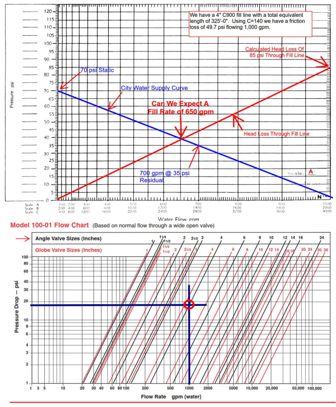
Let's look at the CLA-VAL Model 100-01 automatic fill valve.

[URL unfurl="true"]https://www.cla-valpacific.com/documents/pdf/E-100-01.pdf[/url]

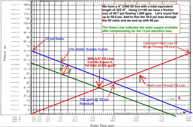
I want to install a 4” C900 4” fill line which has a total equivalent length of 325' which, when using C=140, will give us a friction loss of 49.7 psi when flowing 1,000 gpm.

I know, NFPA tells C=150 for C900 but I want to error on the side of caution so I'll use 140.

When the tank is full the water level is 30'-0” so I need to add another 30*.433=13.0 psi to the 49.7 psi which brings me to 62.7 psi. Using the Model 100-01 Flow Chart it appears the pressure drop through the valve will be 18 psi flowing 1,000 gpm so I have to add that 18 psi to the 62.7 psi giving us a total loss of 80.7 psi so just to be on the safe side let's call it 85 psi @ 1,000 gpm just to be a little more on the safe side.

I am going to graph this on the ^1.85 graph paper

Do you agree that I could expect an automatic fill rate of 650 gpm when the tank is full or am I all wet?

At an automatic fill rate of 650 gpm I can reduce the size of the tank to from 102,240 gallons by 650*60=39,000 gallons to 63,240 gallons? Would I be safe with a 65,000 gallon tank?

FillGraph_p6a8yo.jpg
 
Replies continue below

Recommended for you

Not an engineer or designer or near there,,,

But it appears you are relying on the tank filling,,,, to get your 60 minute run time???

If so,, sounds to me an accident waiting to happen???? Fire happens, and for whatever reason, tank does not fill, and water runs out in say 30 minutes or less???

And the attorneys are knocking on the door at 31 minutes???
 
NFPA 22 said:
4.1.4 A tank shall be sized so that the stored supply plus reliable automatic refill shall be sufficient to meet the demand placed upon it for the design duration.

It's been a long time but I seem to remember reading once where FM Global actually required two fill valves, one being a backup valve, in case one failed.
 
"Reliable supply..."

Not easy to prove.

Plus you say you need 1000gpm @ 85 psi, but you only have 35 psi @700 gpm from the city water supply. A bit of a mismatch there??

Your head kiss through the fill line needs to start at 13 psi for zero flow to allow for the static head. So more like 550 or 600 gpm. Also you are assuming the pressure drop through the valve is linear with flow. Is it?


Your 4" line is way too small for 1000 gpm. Or even 500 gpm. I calculated a velocity of over 7m/sec.You need a 6" and more likely an 8" to get your pressure losses to be reasonable.

Remember - More details = better answers
Also: If you get a response it's polite to respond to it.
 
LittleInch,

I didn't say I needed 1,000 gpm I just picked that number so I could build my head loss line.

@ 1,000 gpm the velocity is at 27.1 fps. Today there's no limit on velocity but back when we had 32 fps and I still keep the 32 fps in mind.

What I came up with was a fill rate of 650 gpm through the 4" line, that is where the two lines intersect, and that number would increase as the tank level lowered.

I should have added a question mark ? where I asked "Can we expect a fill rate of 650 gpm?"

By increase the fill rate it might go from 650 to maybe 680 gpm on a half empty tank but it wouldn't be a huge number.
 
OK

Joys of reading it on a phone but I can see what you're planning to do.

I would still want a historical log over several days of the static water pressure to be able to demonstrate what the actual min pressure is at any time and if I was the person approving this I would want the same.

I agree there is no max velocity, but there is economic one and that is more like 2- 3 m/sec.

Also if this is a potable water supply, I think the water company might make you flow in at the top of the tank with an air gap or insert two flow non return valves which add to your pressure drop. Also what is the maximum they will let you take? I can't imagine they would be too happy with you flattening their system.

but 650 ignores the static head. Your redline needs to start at 13psi at 0 flow rate so the intersection is closer to 600GPM

But try a 6" pipe and see how much more flow you can get for not a lot more cost in pipe. This may or may not be smaller increase than the decrease in your tank size. Do the maths. Maybe not worth it.

Anyway it's the AHJ you need to persuade - Have you asked them?

Remember - More details = better answers
Also: If you get a response it's polite to respond to it.
 
LittleInch,

Not a huge difference between 4" and 6" but here is what I came up with.

We have a 6" C900 fill line with a total equivalent length of 365'-0". Using C=140 we have a friction loss of 9.6 psi flowing 1,000 gpm.

As before when the tank is full the water level is 30'-0” so I need to add another 30*.433=13.0 psi to the 9.6 psi which brings me to 22.6 psi. Using the Model 100-01 Flow Chart it appears the pressure drop through the valve will be 18 psi flowing 1,000 gpm so I have to add that 18 psi to the 22.6 psi giving us a total loss of 40.6 psi so just to be on the safe side let's call it 65 psi @ 1,000 gpm just to be a little more on the safe side.

6_Inch_Fill_Line_soitez.jpg


Not as much of an increase as some might expect. 55 gpm more but when you look at the steep water supply graph it shouldn't surprising.

I'm one to always be on the side of caution because I know I can make a lot of mistakes such as running into an HVAC line or missing a steel beam but so what? Mistakes like that one we have all made and no big deal really.

Two mistakes I can not bare to make and that is 1)not getting the water supply right and 2) not having a signed owners certificate because I do not want to be responsible for the wrong design. Everything else is just a mistake and we all make em.

For this project I know the people at the water company real well and I had them run 5 flow tests at different times over a two week period and the result I am using here is the lowest.

As far as an AHJ we really don't have one and the fire department usually comes to me for answers. The onus is on me which is why I have to do my best to be correct.

Edit: I am actually a little off because while head losses through pipe and valves will vary the 13.0 psi due to elevation will not vary with flow rate. Seems like what I should do is not include that in my calcs line but simply add it to whatever I come up with.

And I do have a call in to Cla-Val engineering so I expect to know more in another day or two.
 
So how long do you calculate to fill the rest of the tank??? To get your required 60 minutes of water??


an automatic fill rate of 650 gpm I can reduce the size of the tank to from 102,240 gallons by 650*60=39,000 gallons to 63,240 gallons? Would I be safe with a 65,000 gallon tank?
 
Your definition of "on the safe side" varies between the two options. You won't get a true option comparison doing it that way.

So for your 4" you calculate 80.7 and round that up to 85 psi - Fair enough - about 6%
But for 6" you calculate 40.6 psi then somehow round that up to 65 psi?? 55% increase or did you really mean 45 psi?

You still haven't taken my point that your red line is not correct - you need to start the red line at 13psi because this is a fixed static head that applies at 10 GPM as much as at 1000 GPM. All you need to do is draw your line differently. don't ignore it or add it on later - just start on the LHS at 13 psi and finish on the right at whatever you calculate the pressure drop to be.

So doing that - 13 psi to 45 psi - I reckon you're looking close to 750 GPM.

So the difference is 750 to 600 - another 150 gpm? Worth it? Your call.

But glad you've made other checks and it sounds like you're taking the right approach overall.

Remember - More details = better answers
Also: If you get a response it's polite to respond to it.
 
LittleInch,

Duh, I don't know how I missed the workings of the 13 psi elevation loss because I do it all the time changing elevation between source and fire pump suction.

I think this is a more accurate presentation of the 4" fill line. I am using 4" just because it makes my curve steeper.

I_Stand_Corrected_vz8mki.jpg


So if the tank is near full I can expect a fill rate of 630 gpm but as the tank leveled is lowered, say half where the elevation loss is but 6.5 psi, I can expect a higher fill rate. Somewhere around 670 gpm perhaps?

cdafd,

In my 46 years in designing sprinkler systems I have purchased exactly one tank which was about five years ago. Everything else has been vertical turbine pumps out of a pond or cistern. Water storage tanks isn't something I have had a lot of experience with.

The one tank I did order, 100,000 gallons, had designed with a 4" fill valve so I wasn't really concerned about the about making up the 2,300 gallons I was short. I was sure the fill valve would deliver the 39 gpm I needed to meet the 60 minute supply mark.

I still don't know how I missed the elevation thing.....
 
I kind of understand what you've done, but I don't think it is correct.

Your supply line (the water main) Blue line is correct. Don't change it.

Your demand line or system curve is not correct. This assumes that the elevation of the water line connection point is at the start of your 325' pipe, your pipe is flat and the static head comes from the head of water in the tank?? This isn't the same as having the elevation of the water line at a different level to the suction of the fire pump - that's something different.

It needs to stat at 0GPM with 13psi because if you don't have 13 psi you won't get any flow. Then at 1000 gpm you should be at your 85 psi pressure which also includes the static head, pipe frictional losses and the loss through the valve.

Then intersection is about 620. Ok, not much difference but it is the correct way of doing it.

Your 6" line on the other hand is about 750 gpm (start 13 psi, end at 45 psi).

Remember - More details = better answers
Also: If you get a response it's polite to respond to it.
 
LittleInch,

The water level in the tank is 30' above the source which is the 13 psi, or green line, I inserted below the blue line. I figure this takes care of any elevation differences.
 
What you are proposing is commonly referred to as a "break tank." One of the requirements is that you need 15 min at 150% of pump rating if I recall correctly for one of the bench marks for a break tank. Water purveyors never want you to draw below 20 psi, so I always stick at that 20 psi bench mark.

Based on flow test data, you have ±840 gpm @ 20 psi. I then just walk back up the curve from there. I figure about 10 psi loss in my fill line. I size it so that I can get no more than that. Also, you have 13 psi for elevation. So, I look at what flow I have at 43 psi. I'm about 600 gpm. Looking at your valve graph, it is about 6 psi at 600 gpm for the float valve. So, I would back that up to what is my flow at 50 psi? I can expect ±500 gpm. I'd give about a 10% buffer and say I've got roughly 450 gpm that I can refill at an appropriate rate.

I'd take the 1700 gpm - 450 gpm and state that I need to store enough water to deliver 1250 gpm for 60 min, or 75,000 gallons. Again, going from memory, the NFPA 20 requirement for a break tank is 15 min @ 150%. Assuming you have a 1500 gpm, you need 2250*15 or 33,750. Since your stored water for the system is ±75k gallons, then you meet your break tank requirements.

This is actually quite a common scenario for projects we see. Now, this obviously has nothing about site fire flow. If you are feeding hydrants downstream of your tank, then you need to do all of the calculations for site fire flow.

Hopefully that gives you some idea of how others address it. Feel free to give me a call if you want to talk about it further.


Travis Mack, SET, CWBSP, RME-G, CFPS
MFP Design, a Ferguson Enterprise
 
Travis,

"Break Tank". I've heard the term many times over the years but never ran into one. So what I have is simply a tank with an automatic fill valve that insures I have my 60 minutes in the event I have a standard ESFR system.

Where is the NFPA 20 requirement for a break tank is 15 min @ 150%? I'm looking.

To be clear all we are doing with a "break tank" is downsizing the tank a bit?
 
Do not have access to current nfpa s

Check under break tank


NFPA 20, Section 14.5.3.1.5 requires “A local visible and audible low liquid level signal shall be provided in the vicinity of the tank fill mechanism.”

The refill system must have a minimum 1 automatic system and 1 manual system. If a minimum 30 minute duration is not provided, a 2nd automatic refill system must be installed.

A break tank must be sized for a minimum 15 minute duration with the pump operating at 150% of its rated capacity
 
I think what Little Inch is suggesting is your Y intercept of the demand curve should be at the elevation head or 13 psi. In the past, i've calculated a number of flow points to plot the demand curve against the supply curve instead of a single point.
 
Status
Not open for further replies.
Back
Top