Eng-Tips is the largest engineering community on the Internet

Intelligent Work Forums for Engineering Professionals

Calculation of air flow through furnace grate

Status
Not open for further replies.

eeprom

Electrical
May 16, 2007
482
0
0
US
All,
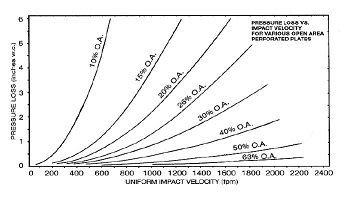
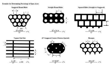
I'm trying to calculate the flow of air into a furnace. The flow of air goes through a grate that comes from a large duct and discharges into the furnace through very small holes. I know the size of the grate holes, and the air pressures on the upstream and downstream sides of the hole, and I know the air density (incoming). The incoming duct is large enough (>1000 times the size of one grate hole) that I can assume incoming velocity to be about zero. I don't have any other information.

I've been trying to apply Bernoulli's equation on this for about a day and I can't see how to find velocity without know the pressure of the air going through the hole.

Does anyone have a way to do this? I'm glad to write a program to solve it iteratively but I can't figure out what equation to use.

Thanks for your help.
 
Replies continue below

Recommended for you

sorry, gotta ask ... why ?

Are you trying to figure out how a flue works ? how a particular flue works ? why your flue isn't working ?

have you noticed that most (old?) stoves have a plate that'll cut-off some of the air ? (the fire needs more air initially, then less once established).

"Hoffen wir mal, dass alles gut geht !"
General Paulus, Nov 1942, outside Stalingrad after the launch of Operation Uranus.
 
No. This is a very large industrial boiler with a 400 HP ID fan. I'm trying to figure out how many pounds power hour of air are getting to the furnace. It seems like this calculation would be simple, but I think it's not.
 
This ID fan is in combustion air supply service ? If so, there ought to be a flow meter on the common air intake to the boiler burners for many reasons, process safety included.
 
If I had that information I wouldn't be asking. Is it possible to calculate the air flow through a grate with the info provided?
 
What is it about the Perforator's Handbook graphical method that you don't like? This is going to get you in the ball park. You may just need to perform some field testing if you want "exact" flowrates.

If you know the %open area (which you can easily determine from hole diameter and spacing, see p.49) and pressure drop you can get a velocity, which can be corrected for density variation.

velocity_qn4nm4.jpg
open_area_rqzdt1.jpg
 
Hi,
Install a pitot tube or other technology on the main duct to get the velocity thus the volumetric flow rate.
Consider getting support from a 3rd party familiar with this type of measurement or a chemical engineer within your organization.
Pay attention to George's comments, he was trying to help you out.
Pierre
 
"This is a very large industrial boiler with a 400 HP ID fan." ... and you're coming to an online forum for answers ?

As noted above, many of your assumptions are greatly simplifying, but also "bad"

What do you expect to learn from this number ? Do you have a number in mind, and are trying to show the system is good, or not good, for the purpose intended ?

The best way to get a number, IMHO and as noted above, would be to run a test.

I suspect your case is quite different to the conventional "flow through a perforated plate". I think temperature effects are driving this, not something taken into account in typical Bernoulli calc.

"Hoffen wir mal, dass alles gut geht !"
General Paulus, Nov 1942, outside Stalingrad after the launch of Operation Uranus.
 
On the other hand, if you have the Q-h curve for this ID fan, all you need is the dP this fan develops, and you'll get the corresponding operating point on the fan curve, which you can then convert to a mass flowrate easily.
 
Forget the holes, take the readings from the entry duct.
Just use an anemometer or pitot tube & read a grid pattern across the duct, from this get an average Velocity figure then multiply this by the cross sectional area & you have flow in CFM or whatever units you require.
Quite simple really.

I forgot to mention that trying the calculate the flow through holes in a grate is difficult, even a precisely machined orifice has a discharge coefficient, trying to calculate from holes in a grate would take a lot of accurate testing.

Best to work from the source of the airflow because what goes in must be the flow through the system.
 
Gentlemen,
I apologize for not being clearer. I wasn't trying to solve the problem of air flow, I was trying to figure out if I could calculate air flow based on orifice size and differential pressure. I now know it's not possible to do this accurately. I wanted this information to do approximate checks of fuel to air ratio.

The best way to do this would be to put a pitot tube in the duct for the FD fan and then check air flow for several fuel rates.

Anyway, thanks again for all of your suggestions.
 
Status
Not open for further replies.
Back
Top