Continue to Site

Eng-Tips is the largest engineering community on the Internet

Intelligent Work Forums for Engineering Professionals

  • Congratulations SDETERS on being selected by the Eng-Tips community for having the most helpful posts in the forums last week. Way to Go!

Calculation of Frame with strut 5

Status
Not open for further replies.

markaugust30

Mechanical
Sep 30, 2017
9
HI Guys!

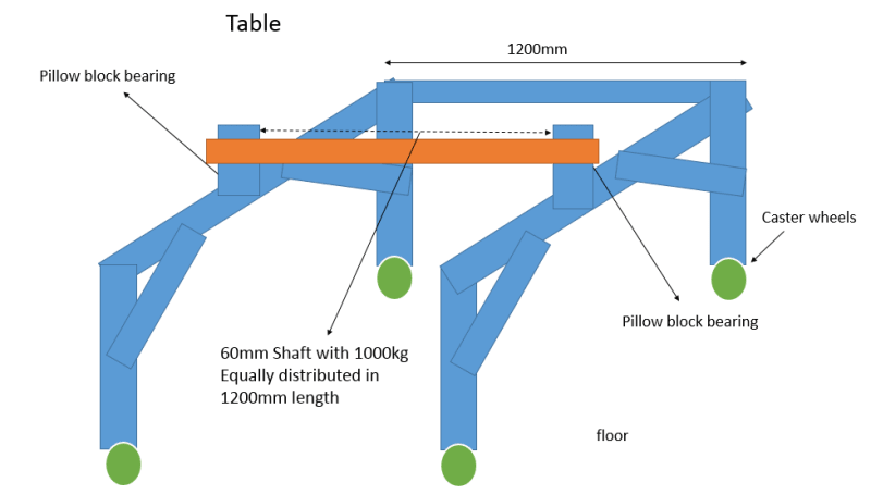
I just wanted to know how to calculate the stress and deflection of a frame shown below.
Capture_rdrrir.png


Thank you for the help. Cant sleep because of this.
 
Replies continue below

Recommended for you

is this school work ?

tell us what is your trouble. what can you do ? (I know how to calc the stress in a beam, but I'm confused about the length and support conditions")

there are several practical ways to solve this …
1) SS at the ends with supports at the diagonals … redundant and messy
2) fixed at all welds (ends and diagonals) … more redundant and messy
3) fixed at the diagonals … redundant but easy to solve. then you have to chase the loads around the triangle.

another day in paradise, or is paradise one day closer ?
 
If this is an engineering problem rather than schoolwork then the horizontal beam is pretty much pinned length 700 and the answer is obvious. If it is schoolwork then I'd say details are missing, the length and fixity of the uprights for a start. Welding 303 will lead to cracking in the HAZ, so the design of the 45 struts is a bit daft.

Cheers

Greg Locock


New here? Try reading these, they might help FAQ731-376
 
is it pinned at the braces ? is the beam length the distance between the CL intersections (closer to 650 mm) ?
or is it a beam on four supports ?
or is the end triangle (brace, vertical, and horizontal) acting as one (so the beam length is between triangle centroids) ?
does it really matter (which assumption you use) ?

Critical section (of weldment) is the lower end of the brace, probably.

Is this a search for "truth" (the most accurate answer), or the most expedient (quickest) ?

another day in paradise, or is paradise one day closer ?
 
You'd have to make a couple of assumptions about the connections in the structure, but in general, I would start with a free body diagram to understand the reactions in the system, followed by a shear and moment diagram, which will give you the shear and moments that you need to perform direct integration to get the deflection of the top beam at any given distance from a selected end (max. deflection would be where the moment is highest on the diagram). You would also have to determine your moment of inertia and modulus of elasticity based on the cross-section and material spec that you've provided.

To rb1957's point, it would help us help you if we understood where you were having trouble (don't know what to do, don't know what NOT to do, don't know HOW to do it, what considerations or assumptions need to be clarified or made, etc).

When you say "deflection of a frame" do you mean deflection of the top beam or the deflection of all members (including supports and braces)? This is just a starting point. You'd have to take into account anchorage, the eccentricity of the load, application of the frame, safety factor, end-fixity, etc.
 
Wow thanks for the replies guys thats fast.

Actually Im trying to make some calculations for the design below. It is a frame with caster wheels, as shown below.
im trying to see how this 45 angle supports will help in the reduce deflection of the beam at load and I need to show it using calculations. The bearing pillow blocks are in the center.
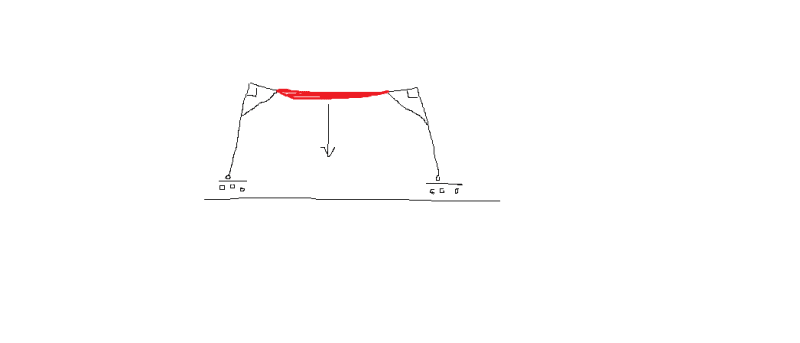
Capture2_gmhpbp.png


I hope you can help me guys on this.
 
Hmm, not a portal. I'd assume the 45 brace made the corners rigid and so the deflection is just bending in the red bit and then a bit more from the corner rotation

FEA_ogjxh5.png


Cheers

Greg Locock


New here? Try reading these, they might help FAQ731-376
 
Hi Greg!

Thanks for your feedback. I guess Im just going to make some calculations on the center (in the red portion you highlighted) with a safety factor of 3. I think it will be a good start for the calculation.
Thank you very much.
 
actually I think looking at just the central span will mislead you. If deflections are critical to you then you need to consider the whole structure.

I would consider the basic frame as a portal frame, with the welds in the corners transferring the moment (two pairs of parallel welds in shear). This would design the welds.
If the welds are not sufficient, or if the deflections are not acceptable, then add the 45deg members, which will make the corner much more rigid.

another day in paradise, or is paradise one day closer ?
 
Hi

I would take the angled corner supports and get them under the pillow blocks and then angle them down to the bottom of the vertical leg. Then connect all the vertical legs together with the section you are using horizontally, so in effect all the castors at the base have a rectangular frame around them

“Do not worry about your problems with mathematics, I assure you mine are far greater.” Albert Einstein
 
Hi rb1957! Ya normally I do that, its just that I want to show in calculation how these 45 braces help in reducing the deflection. Mmmm, well I guess as long as the deflection calculation without the 45 brace is acceptable then should be all good, the 45 braces will be there just for added support.

Hi desertfox! thanks for the suggestion but that would not be possible because i need to slide something on the bottom and it is a space for that.

Thank you all!
 
When and how fast is the Ø 60 mm shaft going to rotate?
Will there be a belt drive or something causing the rotation?
 
OP- you are ignoring the problems with welding 303. The braces as drawn could cause problems, not solve them.

Cheers

Greg Locock


New here? Try reading these, they might help FAQ731-376
 
Hi Greg, I will not be using 303 now sorry about that. Ya 304 or 316 will be the material.
 
Hi T moose, rotation is very seldom, the load is only around 100kg when need to rotate and it will be very slow probably 15 sec/rotation.
rotation will be manual using a gearbox directly mounted to the shaft.
 
OP said:
I want to show in calculation how these 45 braces help in reducing the deflection.
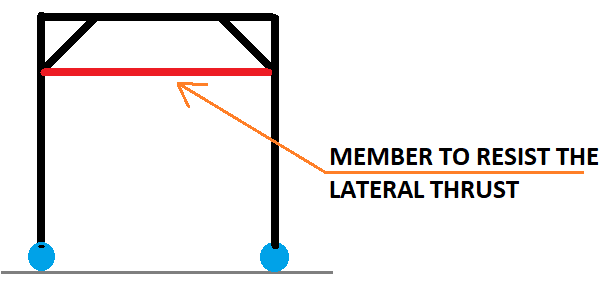
From structure point of view, in your case the contribution from knee braces will not amount to much since the base supports are roller and will simply displace if knee brace take any load. Knee brace will be more effective in reducing the beam deflection if there is a load path to take up the lateral load from the knee brace, such as the frame described by desertfox or the one below.

image_zxruf1.png
 
Status
Not open for further replies.

Part and Inventory Search

Sponsor