Truc Do
Civil/Environmental
- Sep 20, 2020
- 6
Dear all,
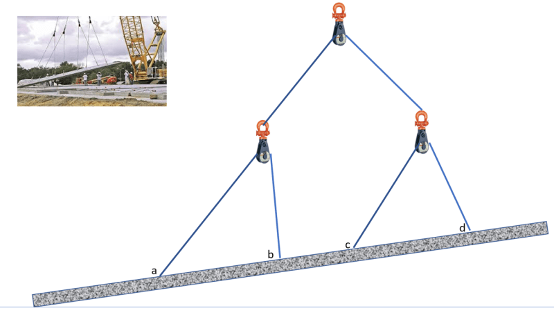
Please help me to calculate load distribution on a multi-lift points when tilting pre-cast panel using multiple snatch-blocks as illustrated in the attached photo.
Thank you very much in deed.
Bets regards,
Truc Do
Please help me to calculate load distribution on a multi-lift points when tilting pre-cast panel using multiple snatch-blocks as illustrated in the attached photo.
Thank you very much in deed.
Bets regards,
Truc Do