Continue to Site

Eng-Tips is the largest engineering community on the Internet

Intelligent Work Forums for Engineering Professionals

  • Congratulations SDETERS on being selected by the Eng-Tips community for having the most helpful posts in the forums last week. Way to Go!

Calculation of the stiffness of a plastic member in a bolted joint

Status
Not open for further replies.

elinah34

Mechanical
Aug 19, 2014
149
Hello everyone,
I guess you all know the familiar formulas for calculating stiffnesses of the bolt and the members in a classic bolted joint. Classic = when all the components (bolt and members) are made of metals (aluminum, steel etc.).
But it becomes complicated in my case - a bolted joint in which the bolt is made of stainless steel and the members are made of plastic (Ultem 1000).
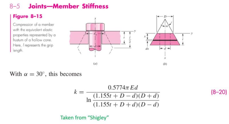
I found out that using the classical formulas (look at the attached file) for calculating the stiffness of the members lead to incorrect results.
Your help will be blessed.
 
Replies continue below

Recommended for you

I haven’t had the pleasure of investigating your case, but my first line of thought would be that with metallic joints you are in the elastic range of the material properties, and your component stiffnesses are linear. With plastics, your stiffness may be nonlinear. In addition, the shape of the compressed region (barrel/cone) may be slightly different, based on the ability of the material to allow the load to propagate out into the compression zone. Food for thought.
 
Hey Stress_Eng (Aerospace)
Everything you wrote is right and correct.
I hope someone will have any idea where to find a reliable source which deals with this issue.
 
Huh?
Nothing was attached.
What “classical formulas”? Reference please.
How do you know the formula results are wrong? Do you have test data?
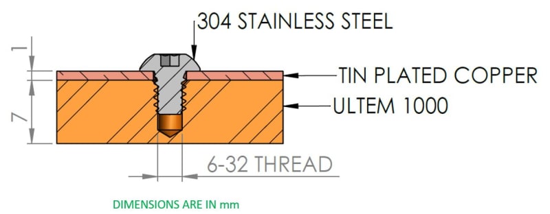
What is your joint configuration? Please show pictures.
 
hey,

I am first going to attach a simplified picture of the bolted joint.
1_gpnszh.jpg


Now, please see the equations I used for classical calculations:
2_n9zcjo.jpg


Finally, I am attaching now a link to an article which has also a formula we used to use with metals:

Using the equation leads to wrong results when comparing it to analysis (FEA) made by an expert who works with me.
 
Ok, thats a lot clearer.
The classical equations do not apply in your case. They are for thru bolts clamping two sheets; in your case one sheet has a tapped hole. Also, the plastic tapped part likely has a nonlinear stress-strain response, complicating the clamp up stiffness.
Now, why do you need to know the joint stiffness?
What makes you think the FEM results are correct vs reality?
What does the “expert” have to say about the joint stiffness?
 
Just going by a quick glance at your picture and attachment, I can add a bit more. With your example being a threaded blind hole, the k value will be different to that for a through hole with a bolt and nut. Going by memory, there’s just one cone emanating from the underside of the bolt head/washer, finishing at half way along the thread length. The finishing length could be influenced by the thread axial load distribution. The finishing length may be slightly less than half way along the engaged thread length. Hope this helps.
 
Shigley's book covers also my case above (a lower member which is threded and not drilled), and not only the case of through hole and a nut.
The difference is the existence of Ultem 1000 as one of the clamped members.
The analysis expert can't explain the difference between the classical equations output and the analysis results.
 
Ok, but again, why do you need to predict the joint stiffness? What problem are you trying to solve?
 
The relative stiffness of the members is needed for calculating the change of the clamping force due to temperature change and/or relexation of the Ultem 1000.
 
Perhaps using the appropriate Shigley diagram would help. The attached paper is also for a condition you don't have.

Each point on the thread exerts pressure towards the interface; that is the direction the cone of displacement will point.
 
elinah34 said:
The relative stiffness of the members is needed for calculating the change of the clamping force due to temperature change and/or relexation of the Ultem 1000.
Ok, then why didn't you state that at the start of this thread?
So you have two analysis predictions of stiffness, a closed form one and a FEM one, that presumably give different results. Both are probably not accurate (and I'd tend to believe the closed form one more than the FEM one given no other info).
If you think the two stiffness results might bound the problem (e.g., one high, one low), you can calculate loss of clamp-up using both values and compare the results for clamp-up change due to temperature change. That might give some insight into whether you have a problem or not.
However, accurately predicting loss of clamp-up due to plastic creep is likely near impossible.
In any case, you are going to have to validate the predictions with some real world test data. One option is to put a load measuring washer under the fastener head and measure load versus time and temperature as a specimen is subjected to temperature change and/or sustained temperature and load.
 
Thank you,

Do you have any recommended manufacturer for measuring washer?
 
Just a suggestion, but have you thought of modelling the plastic as a nut, with an O/D equal to the bolt head and a length equal to the engaged thread length, thereby having an effective length equal to 1/2 the engaged thread length? If the plastic stress strain curve is highly nonlinear, you could calculate a set of displacement values using strain energy, based on incrementally increasing loads, thereby giving you a curve of displacement v load. A spring model based on displacement equilibrium can be set up, including thermal effects. Your model independent variable would be temperature and the dependent variable would be change in preload. More food for thought!
 
Status
Not open for further replies.

Part and Inventory Search

Sponsor