Eng-Tips is the largest engineering community on the Internet

Intelligent Work Forums for Engineering Professionals

CALCULATION OF THRUST FORCE

Status
Not open for further replies.

Kanwarosama

Student
Mar 25, 2024
19
0
0
FI
HI,
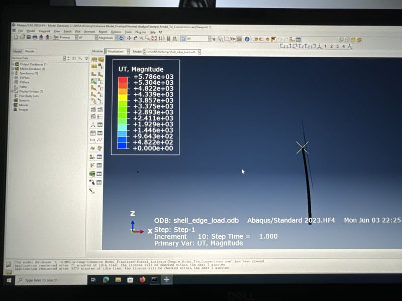
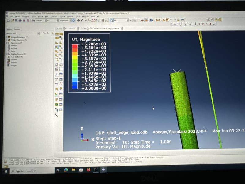
I am doing a project where i need to provide to do the structural anlysis of a wind turbine tower. For this purpose, I calculated the thrust force using the actuator disk theory. The problem with this is it provides me a huge point load of 800 kN. and when i apply this load on the tower it creates a high deflection like 2 meters or so. In my opinion, the problem lies in the use of actuator disk and then applying a huge load as a point force.
Does anybody who has worked with wind turbine analysis provide me with a better idea about how should i apply/calculate the loads so i get reasonable deflection etc.
 
Replies continue below

Recommended for you


How has anyone actually measured deflection for you to match?

150m high tower is going some. Have these actually been built?

Remember - More details = better answers
Also: If you get a response it's polite to respond to it.
 
rb1957 - to produce power there must be a force parallel to the wind direction (from the definition of work), and the only place the force on the actuator disk is resolved in a Newton 2 way is at the motor bearing.

Otherwise helicopters couldn't take off- no axial force, no lift.

Cheers

Greg Locock


New here? Try reading these, they might help FAQ731-376
 
Here's that table. The value of C for a round tube is 3.14.

table_b2.1_qigtvs.jpg
 
the lift vector from a wing can be directed by manipulating the local pressure on the wing. A turbine blades wants torque. How does fwd force help generate power ?

You want to compare a turbine to a helicopter ? Yes, a helicopter wants lift, and has a desperately hard time making it !

The lift for the blade will be mostly in the tangential direction. Yes, there is a component in the fwd direction, but this is essentially wasted.

IMHO, applying all of the force from the blade as a fwd force, bending the tower, is very conservative.

"Hoffen wir mal, dass alles gut geht !"
General Paulus, Nov 1942, outside Stalingrad after the launch of Operation Uranus.
 
The useful work done on a turbine is indeed in the form of torque to turn the generator, but that cannot be achieved without also generating downwind drag.

Think about it - the turbine absorbs energy from the wind, reducing the free air speed downwind of the turbine. That loss of momentum requires a force acting along the axis of the turbine, which is ultimately seen as a horizontal drag load on the hub of the turbine. At the individual blade level, the "useful" force on each blade is the tangential component, but this MUST be accompanied by a "wasteful" drag component which acts in the direction of the wind. The tangential and drag loads are transferred from the base of the blade to the hub. The tangential load turns the generator, while the drag load is resisted by the nacelle and mast.

 
ok then, how much torque is generated if the entire force created by the propeller is fwd ?

Of course there is some fwd force. I have never said there is none. I have said that I think the lift from the blade is rotated to "maximise" the tangential component. I got thinking this way when I looked at a blade and thought "this is the best you could come up with ?". A traditional propeller blade looks very different because it is trying to maximise fwd force (thrust), whereas a turbine blade is trying to minimise thrust (since it isn't useful)

"Hoffen wir mal, dass alles gut geht !"
General Paulus, Nov 1942, outside Stalingrad after the launch of Operation Uranus.
 
And nobody has said the entire force is drag ("fwd" as you call it). Yes, the design of the blade is designed to maximise torque (by maximising the tangential force), but this must be accompanied by a significant drag force component as well. 800 kN (about 80 tonnes) of down-wind drag force doesn't sound unreasonable to me for a machine of this size, which can generate 5 MW or so of electrical power using nothing other than the energy of the wind.

If you have trouble believing this, try inverting the problem. Imagine a helicopter with a 160 metre diameter rotor, powered by a 5 MW gas turbine. Do you think a machine that big could lift 80 tonnes? I can certainly believe it!

 
yes, the OP is saying the entire force on the disc is acting as normal force. Possibly this is correct, he has used the word "thrust", possibly there is a larger in-plane component that hasn't made the calc, possibly the OP (as a student) has overlooked something ?

And please, stop with the helicopter analogies. A turbine is not a helicopter. I believe (incorrectly as may be, but it makes sense to me) that the turbine blade is optimised to the in-plane load, to maximise torque. As I've said, this seems to be a natural thought having seen a blade. A helicopter is trying to create lift/thrust, using little more than a "Rube Goldberg" device.

"Hoffen wir mal, dass alles gut geht !"
General Paulus, Nov 1942, outside Stalingrad after the launch of Operation Uranus.
 
@rb1957:

I believe the analogy between a wind turbine and a helicopter rotor or aeroplane propeller (or even a boat propeller for that matter) is entirely valid.

A helicopter rotor or aeroplane propeller is designed to generate the maximum amount of axial thrust (i.e. axial air flow) using the least amount of motor power / shaft torque.

A wind turbine is designed to generate the maximum amount of shaft torque (to turn a generator) from the available axial wind flow / wind energy passing through the rotor disc.

It's exactly the same engineering principle, but operating in reverse.

The main reasons for the physical differences of geometry of the blades between a boat propeller, an aeroplane propeller, a helicopter rotor, and a wind turbine are because of the vastly different scales, the different materials of construction and manufacturing methods, and the different fluid medium flow speeds / speeds of the blades passing through the fluid medium / flow regimes in which they operate (Reynold's Number).

Long slender blades are the most efficient from a fluid dynamics point of view, but there are practical limits for the size of propellers and rotors on boats and aircraft. (The V-22 Osprey tilt-rotor can't take off and land like a conventional aeroplane; it has to operate more like a helicopter when on the ground.) For wind turbines, the longer the blade, the bigger the rotor disc, and the more electricity generating potential. The maximum blade length is dictated by manufacturing and construction limits, rather than avoiding blade-strike with the ground.

A 160-metre diameter wind turbine operating at 20 rpm in 10 to 15 m/s wind operates in a very different flow regime than a 4-metre diameter propeller turning at 1,000 rpm while flying through the still air at 600 km/hr.


we have different opinions on things, and I don't care to repeat myself again.

"Hoffen wir mal, dass alles gut geht !"
General Paulus, Nov 1942, outside Stalingrad after the launch of Operation Uranus.
 
Status
Not open for further replies.
Back
Top