Eng-Tips is the largest engineering community on the Internet

Intelligent Work Forums for Engineering Professionals

Can a moment force be considered deadweight?

Status
Not open for further replies.

bojoka4052

Mechanical
Oct 8, 2021
108
0
0
NO
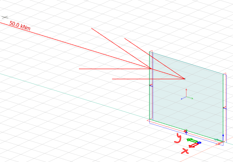
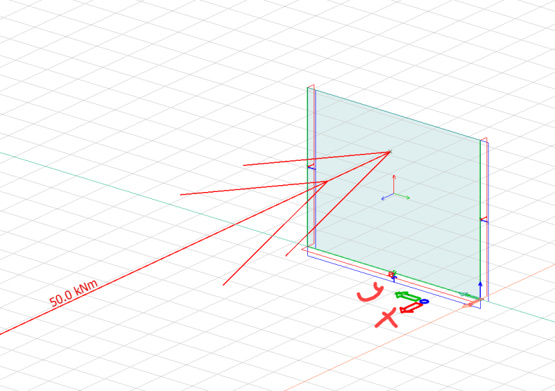
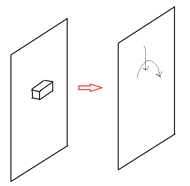
I have a concrete wall, which has an attached concrete structure sticking out inducing moment in the wall. I have modelled the wall without the rectangular bit in FEA programme, Ive simply taken the weight of the rectangle and applied it as point load on the wall and also applied the moment which the rectangle will put on the wall due to eccentricity. I have to make load combinations, and I think it should be fine to consider the point load as deadweight, but would it be okay to do the same with moment?

1_p3zikj.png


Edit: Follow up question:

2_bqjlsd.png


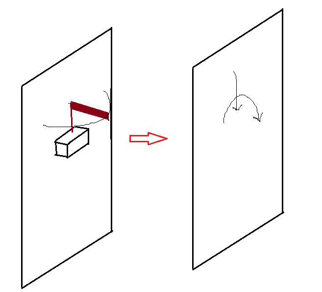
What if on top of the rectangular piece, there is an L-shaped structure, the top part can rotate 180 degrees, what would be the best way to apply it to my model? I was thinking of trying rotating it around and seeing what angle gives the worst case, but should I then apply it as a live load?
 
Replies continue below

Recommended for you

A cantilevered sign structure for example, the sign is considered dead weight... not the snow or wind load applied to it.

Rather than think climate change and the corona virus as science, think of it as the wrath of God. Feel any better?

-Dik
 
Dead loads are considered (relatively) constant over time and usually consist of the self-weight of the structure's components.

Be careful with point loads in FEA, they may cause problems with stress concentrations. In this case, maybe it would be better to include this sticking out part of the structure, even as a rigid body.
 
I get this error when I run my model;

1_y2edz7.png


I know point loads cause stress concentration, but the error in blue refers to something else? Does it mean the results might be wrong since it says equilibrium error?
 
Same problem, model can handle moment force in the y-direction, but applied in the x-direction (parallel with the width of the wall), I get the error you see above.
 
Large nodal displacement and rotations means "ill" constrained model and/or very large force applied in single increment. Did you apply the constraints correctly? Like, for example, for your case fixed the x-constraint? Or it may suggest that large in-plane plate loads along plate, which I suspect, are the cause of no equilibrium and distortion of elements. I suggest to apply load in multiple steps of 10% of load, 20% of load, ...., 100% of load or to your liking number and see the effect.
 
The wall is pinned on left and right side, and fixed at the bottom. In this direction the model runs fine:
2_shui07.png

But when I apply moment in the x-direction I get the error you see above:
1_pxlflz.png

When I look at the displacements of the wall it seems to all be hanging together, nothing crazy going on that I can see. Might this be because loads are applied at one point? But then why does it run without error in one direction but not another?

Edit: When I apply a small enough load in the x-direction, for example 0.1 kNm it runs fine.
 
bojoka4052 said:
Edit: When I apply a small enough load in the x-direction, for example 0.1 kNm it runs fine.

You got the answer. The wall is not strong enough to take 50kNm.

Another thing, pinning side of walls means you have left rotation about z-free? And you are applying moment about Z? Oh no, I am not clear about the notations in your images.
 
When I increase the number of elements I no longer get the "Equilibrium error", but still get the "large nodal displacement or rotation was found".

You can see the axes definition here:
1_tr2um7.png


Its fixed along the bottom edge, so dont think it can rotate about z-axis, even if it is pinned along the sides. What would it mean that the wall cant take the loads? That the model will collapse in real life?
 

What kind of elements are used to model the concrete panel??

From the figures you have posted your Mxx moment is about the drilling dof's of the panel. If the panel is modelled using plates then your problem of large rotations which your solver is complaining about is understandable.
 
Careful with applying moments to a single joint on wall panels/plates. Some software will not transfer moments applied at nodes. Not sure what software youre using but if you tried to do this to a wall panel in RISA 3d for example, you would get a similar error, or the moment would just be lost. It is best to model some sort of rigid link in the plane of the wall and apply the moment to the rigid link, which will get meshed into the wall by the automesher. Will your software show you the generated mesh after solving?
 
You get the warning that you have "large nodal displacement and rotation". I would assume that it means just that. The deformations are so large that the analysis assumptions, probably small deformations, does not apply.

As for your original question, if your deadweight causes a moment, why shouldn't it be included in the deadweight load case? It is obviously part of the load situation.

As I read further in the thread I have to also ask the question already asked, is this a homework assignment?

Thomas
 
Status
Not open for further replies.
Back
Top