Eng-Tips is the largest engineering community on the Internet

Intelligent Work Forums for Engineering Professionals

Can an underground tank be calculated by hand easily? 9

Status
Not open for further replies.

Struct_Dre

Structural
Mar 29, 2019
48
0
0
US
Hello All,

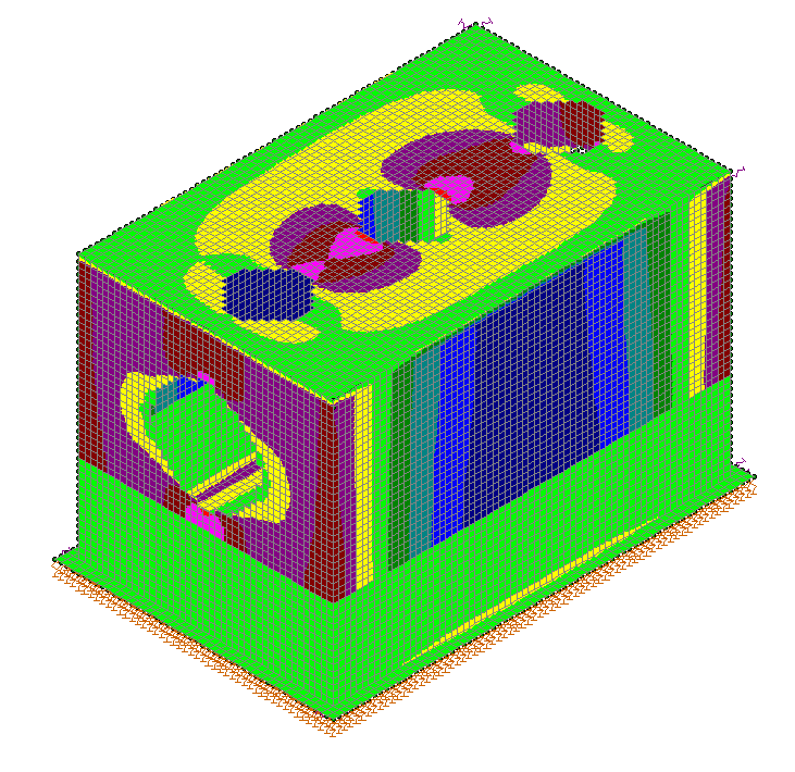
I'm a new engineer who works on tanks often. I was taught to use software for the design of the walls. I typically use the PCA Rectangular Concrete Tanks 5th edition book for my base slabs. I would prefer to do all of my calculations by hand, but I'm not exactly sure how. I think I can break my tank into 3 separate parts (top slab, base slab, and walls) and design each as a concrete beam, but it seems like that wouldn't take into account the higher shear at the corners and openings. This is asking a lot, but can anyone give me a rough list of the calculation process for an underground tank design with openings (for pipes through the walls and access hatches through the top slab)? Specifically for the walls?
 
Replies continue below

Recommended for you

I do a lot of underground concrete tanks. I wouldn't do these by hand, but with some computer modeling.

You could create a simple model of a unit width section of wall as a rectangular concrete frame. Applying loads on the interior and exterior of the frame based on the pressures from soil, surcharge, and hydrostatic forces. Openings will essentially just add additional load on your unit width based on the size of the opening. This should be a close enough approximation and I suppose this could be done by hand if you like analyzing indeterminate frame structures.

What I do is model the wall sections as a series of FEA 2D plates, apply loads to the plates, cut out openings, and analyze the model to get shear and flexure in the structure. I generally conservatively design for the highest forces in the structure for shear and positive/negative flexure. Keeps the rebar nice and easy for the contractor.

When you get into complicated opening conditions (bunch of small openings clustered) this is really the best way to go. Last I checked the numbers you get from a FEA model are roughly the same as from PCA Rectangular Concrete Tanks text. If I recall, a FEA analysis was how they developed their tables.

Ian Riley, PE, SE
Professional Engineer (ME, NH, VT, CT, MA, FL) Structural Engineer (IL, HI)
 
Example of modeling (showing horizontal flexure):

Capture2_p937dv.png


FYI: The reason for the change in flexure in the walls is the upper barrel section has a horizontal joint between it and the lower section. The lower section is cast monolythically with the base slab, thus it's primarially undergoing flexure in the vertical direction.

Good luck analyzing this by hand.

Ian Riley, PE, SE
Professional Engineer (ME, NH, VT, CT, MA, FL) Structural Engineer (IL, HI)
 
I usually do hand calcs early on in the project when I’m getting my initial wall and slab sizes but would turn to a FEM model for the final design. Maybe if there weren’t a lot of large openings would I consider sticking with the hand calcs only. As TME stated large or numerous small openings will affect your stress distribution.
 
Struct Dre....Kudos for wanting to go beyond software (as licensed engineers we are required to validate our software in most US states). It is important that you understand the principles behind the analysis.

What TehMightyEngineer forgot to tell you is that he is a very experienced engineer who has evolved into the convenience of software and has probably done the hand calcs thousands of time, but as we progress in our practices, we have little time to do hand calcs for detailed analysis, only the "quick and dirty" as EDub24 noted.[shadeshappy] Further, our clients are not willing to pay for using a slower process when they expect us to be efficient with our time. Remember....as engineers we have nothing to sell but our time! (well...kinda sorta!)

I would suggest you look through some older engineering analysis texts that were geared to a pre-computer era. Many of the classic texts are still available in earlier editions. These will help you in your process.

Learn the hand methods and that will make you more comfortable with the software approach.
 
Ron makes fantastic points; I am looking at this from the aspect of someone who has done many buried concrete structures and thus I don't really need to double check every model anymore unless I start getting into really weird designs.

As OP is a newer engineer, you should definitely look at hand-verification but even starting out I'd try to use a computer model to help you out in some aspects and the hand-verification to keep you honest. You can definitely come up with a rough hand calc that gets you close enough to give you an idea of the sizes/rebar for a buried structure.

If you want, post your hand calcs here or post the details of the structure you are analyzing and we can help you verify the design.

Ian Riley, PE, SE
Professional Engineer (ME, NH, VT, CT, MA, FL) Structural Engineer (IL, HI)
 
It is important to do the hand calculation to feel about your structure. for tanks it is very easy i do it be excel sheet in case of trial for sections. With PCA it is easy but you need to handle your structure system as transfere the slab load on the walls then design the walls in two direction as per the walls dimensions PCA book is very pioneer on that. In some complicated you can go through any software package. This book provide you a hand calculation and excel sheet.

 
I suggest:
Moments and Reactions for Rectangular Plates
Engineering Monograph No. 27
by
U.S. Department of the Interior Bureau of Reclamation

It's online somewhere.
 
I love this place :) Thanks for all of the advice! I'll do some calcs at home (on my time haha) and post them here after I submit the to the client.
 
I second the Engineering Monograph No 27 document. It has some good tables similar to the PCA rectangular tanks book. My company actually developed an excel program for rectangular plate analysis based off that document. I use it quite often. The PCA ciruclar tanks book is also good if you ever do circular tanks. What would be helpful is if you developed some sort of excel macros program. It'd be a good way to learn the theory behind it and then you have an efficient 'quick and dirty' way to estimate wall thicknesses and rebar spacing for future projects. Early on in my career I would do that a lot when I was learning. I developed excel sheets for beam design, concrete column P-M diagrams, T-beams etc.
 
Take a look through Roarks (formulas for stress and strain). You can try to approximate your tank with a combination of flat plates or a pressure vessel - and even though the formulas are for an isotropic material, they should still give you correct bending moments.
 
Sorry to be a little late to this thread, but I design subgrade tanks exactly the way TehMightyEngineer does it (except I do not use that fine of a mesh!--my finite elements are usually about 1' X 1').

Just like any other structural engineering, find quick and dirty ways to check computer results. In this case, the worst horizontal pressure is near the bottom of the tank, so you could check a horizontal one foot strip for a moment of w[sub]u[/sub]l[sup]2[/sup]/10, and a shear of w[sub]u[/sub]l/2 (shear quite often controls the tank wall thickness). But I have found the most difficult part of tank design is designing for vehicle loads on top of the tank (I have done them for airfields--the wheel loads are enormous!).

DaveAtkins
 
Dave said:
except I do not use that fine of a mesh!--my finite elements are usually about 1' X 1'

I used to use a 1' mesh but I've found a 3" mesh doesn't take too much longer to run and better captures effects around corners of square openings and the like. You're right though that it's probably overkill and generally you'll capture the correct moments and shears.

Dave said:
I have done them for airfields--the wheel loads are enormous!

Ugh, right there with you. Thankfully my structures were all round so other than the top and bottom slabs it wasn't that bad. Still a huge pain, though.

Ian Riley, PE, SE
Professional Engineer (ME, NH, VT, CT, MA, FL) Structural Engineer (IL, HI)
 
Status
Not open for further replies.
Back
Top