Continue to Site

Eng-Tips is the largest engineering community on the Internet

Intelligent Work Forums for Engineering Professionals

  • Congratulations GregLocock on being selected by the Eng-Tips community for having the most helpful posts in the forums last week. Way to Go!

Can I improve this mechanism? (Perpendicular Linear Movement)

Status
Not open for further replies.

zeroburn315

Aerospace
Sep 26, 2013
13
I have already made a machine with this mechanism. Unfortunately I cannot change this mechanism however I can modify the design of the part which is rotating. (Cannot change the linear part)

Video Link


Can anyone help me do the calculation or design the most optimal solution which will give the smoothest linear movement for this mechanism. I am not able to figure out what shape will I make that will reduce the stresses. I tried many shapes however still not a significant difference.
 
Replies continue below

Recommended for you

Hi zero

I watched the video but it doesn’t tell anything as to why the bell crank lever is under stress, can you provide more information?

“Do not worry about your problems with mathematics, I assure you mine are far greater.” Albert Einstein
 
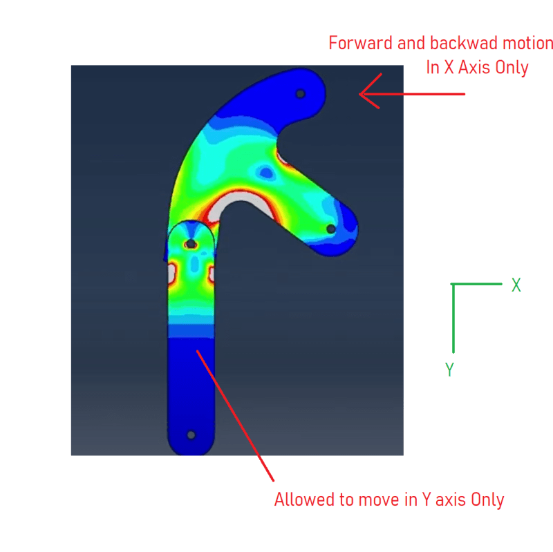
Sorry my bad, I forgot to mention that there are boundary conditions applied as follow:

Mech_vwwr9q.png


The restriction of movement is what is generating stresses.
 
Can you provide the setup snapshot of this model with BC's And loads applied, to better understand the problem? It looks like holes are constrained which may induce stresses. The pin joint conditions need to be considered for this simulation.

If there is no restriction in movements, I think there will not be much stresses.
 
I don't see how the link does what your constraints define ?

This is a simple rotational link. Maybe you mean the hole at the bottom of the vertical link moves vertically (so the link itself moves slightly side to side).

I'd've thought that you needed a four bar linkage to do what you want.

another day in paradise, or is paradise one day closer ?
 
to do what you say the two holes (other than the rotational one) must be bigger than the related pins because they are rotating (that is none vertical and horizontal displacement)
 
You're boundary conditions are not correct.

Because arcs are not straight.
 
Zeroburn315:
You need a straight horizontal force link to the right of the upper right pin hole. You need linear sliding guides at the outer end of this force link and the vert. force link on the lower left. These sliding guides will make those end motions truly linear, and the force links will oscillate a degree or two about their central axis. The bell crank lever could be made larger to reduce its stresses. You should increase the radius of the two inside curved corners, which will reduce the stresses. Or, in the extreme just make the crank a square pl. (+ or -) by joining the curved end of the lower left lever to the center pivot lever by a straight edge line, and the center pivot lever to the curved end of the upper right lever with a straight edge line. This eliminates the inside radiused corners which are almost always stress raisers.

 
If you are already happy with the mechanism then you are o.k. with the slight +/- y motion of the upper link pivot point? And the slight +/- x motion of the vertical link pivot point? And the mating links, they are allowed the same DOFs? Looks like you have some red stress at the pin for the vertical link. I could see that occurring if the vertical link was not allowed the +/- DOF in the x direction.
 
if you constrain the upper lug to move in the horizontal direction, well, then it isn't rotating about the center. As it translates it'll be opening up (and stretching) the arm.

Your simple mechanism isn't doing the motion you want it to do. Now you can modify your mechanism so it does ...
make the end holes oversized (or slotted) so the pin can move horizontally as the arm rotates, or
(I had an idea about using eccentric bushes, but that may not work).


another day in paradise, or is paradise one day closer ?
 
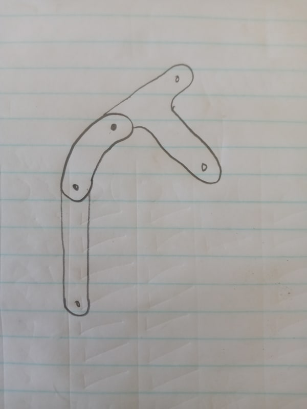
20220212_141435_q4um0e.jpg


I think your best bet is to break the mechanism up like in the picture.
 
My mantra over the years - everything works when there's no scale. Spread the coordinates enough and it should be fine.

Was this the inspiration for the mechanism?

pumpjack_euebsh.jpg
 
Your video shows the upper hole moving along a circumference, which is what your mechanism is only capable of doing. You show a pivoting mechanism, so stuff have to move along a circumference. I think you want a Scott Russell linkage: Note, however, while converting rotation to both vertical and horizontal motions works over the full range of motion in the animation, converting vertical to horizontal or vice-versa cannot be done over the full range shown, since the fully extended mechanism in vertical or horizontal are singularity points; small offsets can allow motion, but only with extremely large forces. Nevertheless, with the small link at 45 degrees, the mechanism can, and will, convert vertical to horizontal and vice-versa.

TTFN (ta ta for now)
I can do absolutely anything. I'm an expert! faq731-376 forum1529 Entire Forum list
 
IMHO, to do the motion you describe, you need a four bar linkage.

another day in paradise, or is paradise one day closer ?
 
Status
Not open for further replies.

Part and Inventory Search

Sponsor