Continue to Site

Eng-Tips is the largest engineering community on the Internet

Intelligent Work Forums for Engineering Professionals

  • Congratulations KootK on being selected by the Eng-Tips community for having the most helpful posts in the forums last week. Way to Go!

Can someone help me figure out what is going in this pumping system? 5

Status
Not open for further replies.

jimmy001

Mechanical
Jul 11, 2017
9
Hi all,

I am an intern working on this project, I am wondering if you can help me out with figuring out this pumping system?
Here is a sketch for the system: 2 identical pumps connected in parallel drawing from an atmospheric pressure storage tank, pumping to two discharge locations, and there is another 2'' re-circulation line with a around 60% closed manual valve at the end of the line.
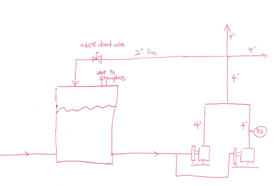
current_sketch_for_help_p99mui.png


There is only one pressure gage on one of the discharge lines. The pressure reading is 80 psi. This one pressure gauge was newly put in so it shouldn't be defect.

Here is the pump curve for the 2 pumps. (Both have 8'' impeller diameter)

[URL unfurl="true"]https://res.cloudinary.com/engineering-com/image/upload/v1501764838/tips/2K4x3-10_Curve_at_3550_rpm_esa28a.pdf[/url]

I added the flows together and made a pump curve with 2 pumps in parallel here.
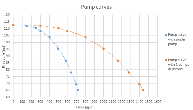
pump_curves_r8qpdq.png


Here is what's weird. The two discharge locations are only taking in on average 400 gpm of flow, maximum 500 gpm. The discharge pressure is 80 psi, although there is no suction side pressure gauge, but since the suction side comes from an atmospheric storage tank,the total pump head should be around 80 psi, which corresponds to around 1250 gpm. However I doubt that that the 2'' recirculation lines with a 60% closed valve is carrying the rest of the 750 gpm. I explained this to a pump mechanic at the plant, and he told me that water might be recirculating inside the pumps. I looked up suction and discharge recirculation within pumps, and found out that it's not good lol. However I'm not sure if 750 gpm could just recirculate within the two pumps.

I know that's not a lot of information to really fully comprehend the issue, but since I am just an intern I can't ask for more pressure gauges or flow meters. Wondering if you can help me figure out what is happening here; are the pumps performing below expectation, is 750 gpm just being recirculated through the 2'' line or is 750 gpm recirculating inside the pumps? Which scenario is more likely?

Thank you all in advance.
 
Replies continue below

Recommended for you

Some additional information is needed to start venturing a guess at your scenario here:

Do you know how the pumps are controlled? Do they have VFDs? What type of pumps - centrifugal? Have you confirmed both pumps are running at the same time?

What type of manual valve is on the recirculation line? What can you tell us about the system served by the two four inch discharge lines - constant or variable flow resistance?

What feeds the atmospheric tank and what is the flow rate into it?


The velocity I calculated in the 2" line at 750 gpm is around 20m/sec. High, but not unbelievable.

A 60% open valve is essentially open if it is an isolation valve.
How long is that 2" line?

At 80 psi the pumps are at the end of curve and will not be recycling internally. Is the gauge at the same elevation as the pump header?

Plant operators often have no real comprehension about pump systems, they just find a way to make something work and then stick with it.

As it stands you're burning a lot of energy for no benefit. At that flow you only need one pump, but that re-circulation line is your killer. That's why I don't like them if they are not properly controlled.

Remember - More details = better answers
Also: If you get a response it's polite to respond to it.
 
@KoachCSR

No VFD, they are on 24/7. Both are centrifugal pumps, I am certain that both pumps are running at the same time, both pumps were quite noisy and the the motors were both running.

The manual valve on the recirculation line is a 2'' ball valve. The 4'' discharge lines both have variable flow resistance, because the discharge locations don't need water all the time, so the flowrate is not consistent. On occasions, both 4'' discharge lines would have no flow in them at all. However, the discharge pressure gauge always reads ~80 psi.

The atmospheric tank is fed by a 6'' line that draws from city water supply. There is a flow meter that only records the totalizor flow, and the average supply rate is ~230 gpm.

Thank you.
 
First thing to look at is the possibility that the recirc. line discharging into the supply tank is driving lot of air into the tank which in aerating the supply and the pumps are not performing as they should be. You need to check power input to the pumps to see if they are on curve.
Try closing the by-pass valve completely and see what happens to the flow rates.
Are both discharge lines of equal length and discharge levels the same?
Don't assume a new gauge is OK.
If you are only allowed pressure 1 gauge, have a tapping point put into each of the discharge pipes and the recirc. line and check each line separately.
Are both pumps operating in the correct direction?

a few random thoughts for you to get on with.

It is a capital mistake to theorise before one has data. Insensibly one begins to twist facts to suit theories, instead of theories to suit facts. (Sherlock Holmes - A Scandal in Bohemia.)
 
@LittleInch
@KoachCSR

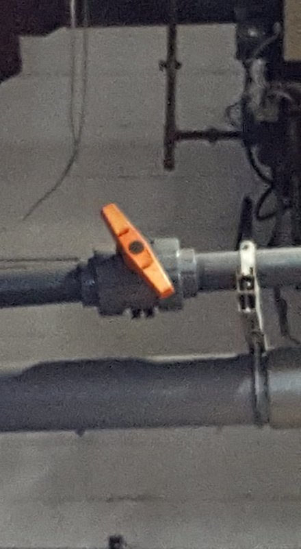
Correction about the manual valve, it is currently positioned like this
manual_valve_opening_position_hpnxex.jpg


And the two inch line is pretty long, it is a safety shower loop, and it recirculates around the whole plant, so probably around 4-500 ft minimum
Sorry, and thank you.
 
I've never looked - but there might be charts / tables around that will give you an idea of flowrate thru the valve at different pressures.

It is a capital mistake to theorise before one has data. Insensibly one begins to twist facts to suit theories, instead of theories to suit facts. (Sherlock Holmes - A Scandal in Bohemia.)
 
With both pumps running continuously, LittleInch is correct - you're burning a lot of energy with no benefit. Also, the velocity in your recirculation line would be screaming when neither of the 4 inch lines has flow - upwards of 50 ft/s; it would be vibrating like crazy.

I find it highly suspicious that your pressure gauge is reading a constant 80 psig, even when you are utilizing pure recirculation; I suspect your gauge has an air pocket somewhere that is causing it to constantly read 80 psig, even if the pressure is fluctuating up or down at different conditions. As conditions change and the system resistance seen by your pump changes, so should the operating point on the curve - since your manual valve is not modulating to control flow by varying resistance and you can have no flow down each 4 inch flow path, your gauge shouldn't be consistently reading 80 psig.

Edit:
Just noticed your explanation that the 2 inch line is a safety shower loop that you expect to be at least 400 ft long...this is perplexing, given that the pressure drop in 400 feet of 2 inch pipe at the full 1250 gpm is much more than 80 psig. Are there booster pumps located anywhere in the flowpath of the 2 inch line? Any control valves (such as pressure control valves) which may be regulating the discharge of the pumps?
 
"However, the discharge pressure gauge always reads ~80 psi."

That doesn't look good. Is it actually connected to the pipe( isolation valve on?)

With only one reading to go on it's not reliable enough.

As artisi says, try and check out the motor input - if you can get to the switchboard then it will show you amps and volts for those motors normally.

three questions

What is the water level in the tank relative to the pump inlet? (where positive is the water level is higher than the pump)
Is the pressure guage on the same elevation as the pump discharge nozzle ( give or take). If not what is its elevation compared to the nozzle
How are you measuringing outflow?


Remember - More details = better answers
Also: If you get a response it's polite to respond to it.
 
On what basis are you assuming the pumps are running simultaneously? Is this an observation?
Such pump configurations are usually designed to only run one pump at a time in a lead/lag configuration. (Lead/lag meaning that one pump will operate for a specified period of time, then the other. This provides redundancy should one pump fail to work and equal wear and tear between the pumps.)

Where did you get that the pumps are trying to push 750 GPM? This is off the recomended operting curve provided by the manufacturer and according to your generated curve can only generate 65 psi of head. This obviosly isn't happening as indicated by the one pressure gauge you have.

400-500 GPM is right in the sweet spot of the manufacturer's curve for an 8" impeller. And should be generating (240 FT HD, 104 psi). Is the 80 psi with the pump running? Where are the pump relative to the tank, above/below, how far from?

You're in intern? Where is your mentor/senior engineer? Why isn't he helping?
 
The atmospheric tank water level is around 8 ft positive relative to the pump.

The pressure gauge is right at the discharge nozzle of the pump, before the isolation valve. the reading fluctuates up and down a little bit, but always reads around 75-80 psi range.


no booster pumps and no control valves anywhere after the two pumps, the 2'' discharge from the 2 pumps just circles the whole plant.

There are flow meters on one of the discharge location, reads both instantaneous and totalizer flow, need around 350 gpm when required; the other discharge location flow rate was estimation, but it would not be anything drastic, it's not constant, but probably around 100 gpm maximum.

Another thing is that, I did not observe any check valves on either of the pump discharge lines. Could it be that one pump is feeding into the other? I am not so sure.

@dbill74

Yeah I observed that they are running simultaneously, noises coming from both motors and i could see the spinning. On the parallel pump curve against 80 psi there should be 1250 gpm of flow. the pumps are 20 ft away from the atmospheric tank, 6'' suction line.

I am an intern and I could not receive much help unfortunately.


Thank you
 
Hmmm, Well unless there is a leak somewhere or some other user is taking water then the re-circulation line is your only current option.

However looking closely at your pump curve these pumps are 30 years old??

They could have been altered or changed, the impellors could be seriously damaged or motors changed. Ask an old hand if the pumps have ever been changed out or modified - see if there is a plate on the pumps showing what size is actually installed.

difficult to do much more without some site investigations and doing something like isolating the pump and the recirculation line and doing some flow tests to see if each pump is actually doing what you think it is. An easy one is to isolate the pump with the pressure gauge and see what pressure it creates at no flow for a few seconds. This assumes you have some isolation you haven't shown on your sketch.

Not having a non return valve isn't great as it makes single pump operation difficult, but at the point where you think you are on the pump curve you won't be getting any revers or no flow in one pump or the other - that's only when you're operating in a flat pump curve area.

The going around in the wrong direction for a long time is also a possibility - check motor rotation arrow if you can see it.

Let us know how you get on.


Remember - More details = better answers
Also: If you get a response it's polite to respond to it.
 
I asked the local pump representative and our mechanics, and got told the impeller size was 8 inch.

I shut down one pump and closed the discharge and suction valves for that pump (not running), and saw that the pressure on the pressure gauge dropped down from 80 to around 65 ish. I then closed the isolation valve on the discharge line for the one pump that is running, and saw the pressure gauge jump up from 65 to 80. I am assuming this is the dead head pressure, since no flow is generated? So based on the pump curve, the supposed dead head pressure should be around 112 psi, is it that the pump are running below expectation, possibly since they are 30 year old?

I couldn't make out which way the motor was spinning.

I couldn't get the volts and amps at the moment.

@LittleInch

You said "at the point where you think you are on the pump curve you won't be getting any revers or no flow in one pump or the other - that's only when you're operating in a flat pump curve area." Could you explain to me a little bit more, why it wouldn't be the case of pump internal circulating, or one pump discharging into another pump?

Thank you guys for the responses. I will be back tomorrow.

Edit:
Hi guys, another update.

I was able to get the volts and amps. Both 60A and 463V. P=VI=27780W=37.25HP. On the pump curve, 37.25BHP corresponds to around 390 gpm and around 240 ft of head which is 104 psi for just one pump. So if two pumps in parallel are using 37.25BHP each I should get 780 gpm against 104 psi right? and since the gauge is only reading 80 psi, the pumps are under performing?

Thank you
 
To the OP, the pumps are in parallel not series.

Ted
 
@hydtools

Hey thanks, didn't notice I made that mistake.
 
Can you get access to the recirc line at the tank? Perhaps you could take some estimate of the flow there (5 gal pail?).
With worn impellers a pump curve would show a lot less head, and a little less flow.
Your shut-in pressure value proves that either the pressure reading is bogus or (most likely) the pumps are seriously under performing.

= = = = = = = = = = = = = = = = = = = =
P.E. Metallurgy, Plymouth Tube
 
Check also all strainers. Blow them out. Since the average makeup water flow is about 230 gpm the pump flows should be close to this otherwise the tank would quickly empty.
 
IMO, there is a big discrepancy of the field system test from the original pump design. There is a lack of the inspection to verify the actual conditions wrt the pump P-Q curve. Also, without calibrated instrument and/or proper measurements, it's difficult to figure out the actual pressure and flow of the lines. It could be guessing for many possibilities.
 
why 750 gpm? have you used 1250 x 60% (closure of the valve) = 750 gpm ?
This uses the assumption that your manual valve has linear characteristics. It maybe not the case. I doubt such a small valve has some kind of special characteristics but you could end up well of the mark ; and even if the difference turns out not to be that big - at least it is a matter of consistency in the approach. I agree with Artisi's post above to look up into tables in order to estimate the actual flowrate.

Quoted
However I doubt that that the 2'' recirculation lines with a 60% closed valve is carrying the rest of the 750 gpm
Unquoted

What is the basis of this doubt? did you make any attempt of physical measurement (using an instrument) or is it just intuitive?

 
Until you fully understand the performance of each pump individually, and how each pump interacts with the system and how the system interacts with the pumps you are running in circles and spinning wheels.
You need a methodical not shotgun approach to the problem, that's assuming there is a problem.

It is a capital mistake to theorise before one has data. Insensibly one begins to twist facts to suit theories, instead of theories to suit facts. (Sherlock Holmes - A Scandal in Bohemia.)
 
Status
Not open for further replies.

Part and Inventory Search

Sponsor