Continue to Site

Eng-Tips is the largest engineering community on the Internet

Intelligent Work Forums for Engineering Professionals

  • Congratulations MintJulep on being selected by the Eng-Tips community for having the most helpful posts in the forums last week. Way to Go!

Can someone help me read how this differential relay is set? 2

Status
Not open for further replies.

bdn2004

Electrical
Jan 27, 2007
794
The actual trip time? It is a GE PVD Differential Relay.

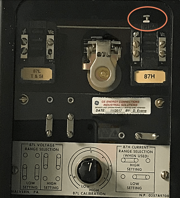
See the attached (2) pic file of the relay and a cut sheet.

It is connected to a 3000/5 CT, on a 12.47kV bus. The card on the front says it is set at 135V, and 2A.
The cut sheet says its typical operating speed is 20ms (1.2 cycles) at 4X pickup.

Our data from a test report shows that this is set at 0.083 seconds (5 cycles).


 https://files.engineering.com/getfile.aspx?folder=2a91f5ff-e74f-40a6-909c-78934129769e&file=Full_page_photo.pdf
Replies continue below

Recommended for you

I'm guessing you meant 1.2 cycles instead of 12 cycles.
Here is the time curve from the PVD manual. I don't see how they were getting the relay to trip at 83ms, unless they were measuring the trip time from the lockout relay possibly.
asdf_r4chkc.png
 
Both the 87L and 87H are set to Low Setting via the range selection bars.
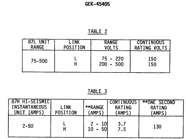
The 87L setting is set by turning the black knob in the center. Low range is 75v to 220v. I'm not sure what the dots around the dial refer to.
The 87H setting is set by adjusting the core of the 87H unit (screw on top) up and down. Low Range is 2 to 10 amps.

asdf_azrssv.png

abcde_rldqnv.png
 
Thanks. 2A on the 600:1 CT would be 1200A. The pickup then is 1200A...? how does that correspond to the info on that graph and on that card on the relay?
 
It doesn't, don't worry about the primary current if you are just testing the relay. The relay is tested in secondary units, 135V and 2A.
 
I doubt you can push 2 A through it during testing.
 
The voltage operates the timing unit at 135 volts, so it would operate at 270 volts (2x 135v) in 25 m Seconds. The 2 amps is in series with the thyrite and picks up the instantaneous unit.

David
 
I'm not testing the relay.

I just want to know what the response time is of this relay and compare it to what we were told it is (0.083 sec) from this information.

On that graph....time is on the Y-axis. Is it time on the X-axis too? Does the response time have to be somewhere on that curved line ?

 
In case of an actual fault I would expect the relay to operate in about 1 cycle (0.017 Seconds). Time is on the Y axis, fault voltage on the x axis, I would expect the CT's to provide 4-5x fault pickup voltage.
 
Fault voltage? That's not very intuitive nor do I understand how any of this stuff relates one to another. It's obvious this is gonna take some study on my part. Again, all I want to do is verify the number we already have. Thanks anyway.

 
The way the bus differential protection works is the CT's are in parallel around the zone of protection, the currents add to zero as long as no fault exists. When there is a fault, the CT is essentially open circuited and produces a high voltage that goes to the relay. The relay opens a lockout relay that trips the breakers in the zone and shorts out across the relay inputs removing the voltage from the relay. It's very fast protection and works well. The relay is set based on the open circuit CT voltage and fault current.

One cycle would be a typical expected time for it to operate the lockout relay. The table shows it operating in 15-20 m seconds, which is right.
 
The test showing it operating in 5 cycles is slow due to limitations of the test set, during a fault it would operate faster because the CT's would cause the voltage to build up faster. During an actual fault the relay would operate in 15-20 mSeconds.
 
Dear Mr bdn2004

Q. Fault voltage? That's not very intuitive nor do I understand how any of this stuff relates one to another.
A. This is a [voltage] operated relay even though it is connected to CT with [current] as the input measuring value. The conversion from [current to voltage] is done (internally) by the relay design. With the known [current input to voltage output ratio], it is possible to set/calibrate the relay based on the [voltage] value. With the set (voltage) value e.g. 135V, the relay does [not] pick-up i.e. [no] tripping at 1x 135V. However, the relay picks up with 30ms time delay at 1.5x 135V, 25ms time delay at 2x 135V and 18ms time delay at 4x 135V etc., with [minimum time delay] of 17ms approx. even the voltage had exceeded 6x 135V.

Che Kuan Yau (Singapore)
 
Ok I’m going to try to explain what I think you are saying…please tell me where I’m wrong. Thanks!

1) When voltage appears across the operating relay coil – the relay is energized and closes the contacts on the relay – like all relays.

2) The two current transformers are wired so that during normal operation they oppose each other through that operating relay coil making the net current = 0 and therefore 0V and no operation.

3) If there is a fault inside the protected zone, there is a mismatch in the secondary currents and current flows and creates a voltage. At a minimum voltage of 135Volts across the operating coil, the relay will trip.

4) The greater the fault current the greater the voltage that is developed across the relay coil and the quicker the operation. Thus the X-Axis of the graph and the inverse-relationship of the trip time-voltage curve.
 
Dear Mr bdn2004

Introduction: Ok I’m going to try to explain what I think you are saying…please tell me where I’m wrong. Thanks!

Q1) When voltage appears across the operating relay coil – the relay is energized and closes the contacts on the relay – like all relays.
A1) Wrong. No. The relay does [not] operate at the (set voltage value). The relay operates only when the voltage exceeds the set value by 1.3 times approx. The higher the voltage value [above the set value] the shorter the tripping time (see reply by Messrs JG2828 and che12345)

Q2) The two current transformers are wired so that during normal operation they oppose each other through that operating relay coil making the net current = 0 and therefore 0V and no operation.
A2) Right. Yes.
Note: The corresponding CTs at both ends (of the line) shall be of the same manufacturer/ type/model with the same current ratio e.g. XA/YA , class e.g. X P Y , burden e.g. XY (VA), saturation voltage characteristic e.g. XYZ (volt), secondary winding resistance e.g. XY(ohm), with the correct polarity e.g. input P1 to P2 output S1 to S2 and on the same line/phase conductor e.g. (L1) etc.

Q3) If there is a fault inside the protected zone, there is a mismatch in the secondary currents and current flows and creates a voltage. At a minimum voltage of 135Volts across the operating coil, the relay will trip.
A3.1) Right. Yes, when there is a mismatch in the secondary currents and current flows and creates a voltage.
A3.2) Wrong. No, the relay [does not] trip at the set voltage of 135V. The [minimum operating voltage] is at 1.3approx time the set value i.e. 1.3approx times 135V.

4) The greater the fault current the greater the voltage that is developed across the relay coil and the quicker the operation. Thus the X-Axis of the graph and the inverse-relationship of the trip time-voltage curve.
A4.1) Right. Yes, the greater the fault current the greater the voltage that is developed across the relay coil and the quicker the operation.
A4.2) Right. Yes, inverse-relationship e.g. there is [no] tripping at 1 time of the set value, but with delay-time 25ms at 2 times or delay-time of 20ms at 3 times the set (voltage) value etc...

Che Kuan Yau (Singapore)
 
Ok great posts

.....then as a summary to all this:

The differential relay itself will trip in approximately: 0.017 seconds (1 cycle)... (although from the above discussion it seems worst case would be 25ms delay?)

The lockout relay will trip in approximately: 0.017 seconds (1 cycle)
This is in the software on the bus - so we add in the breaker opening time: 0.05 seconds (3 cycles)

Essentially 5 cycles = 0.083 seconds, which is what we've got and what I was trying to confirm.


Dear Mr bdn2004
Introduction: .....then as a summary to all this:

Q. The differential relay itself will trip in approximately: 0.017 seconds (1 cycle)... (although from the above discussion it seems worst case would be 25ms delay?)
A. Wrong. The relay [does not] pickup/trip (at all) at 1x setting. It [picks up] at > 1.3x approx the set value and it would take a time delay of 40ms approx to trip. This would be the case of a (light) fault. At 2x the set value, it would trip at 25ms etc. etc. The "worst case" i.e. with (heavy) fault when the voltage is = or > 6x or >> 6x the set value, the tripping time delay would remain 17ms approx; and would [not] be (any much faster).
FYI: It would be [wrong] to presume that under "worst case" i.e. (heavy) fault, the relay would take [ "maximum" time delay] of 25ms.

Che Kuan Yau (Singapore)
 
ok, I see that. Let me revise this...

The differential relay itself will trip (worst case, slowest time) on a light fault in approximately: 0.040 seconds
The lockout relay will trip in approximately: 0.017 seconds (1 cycle)
This is in the software on the bus - so we add in the breaker opening time: 0.05 seconds (3 cycles)

0.04 + 0.017 + 0.05 = .107 sec

Thanks!


Dear Mr bdn2004

Q1. Let me revise this...The differential relay itself will trip (worst case, slowest time) on a light fault in approximately: 0.040 seconds.
A1. Wrong.
1. With light fault < or =1x setting, [no] tripping [indefinitely].
2. With light fault at 1.3approx setting (only), the tripping time (is) 40ms.
3. See tripping curve by Mr JG2828 for any other multiples of set value.
4. For "worst case" i.e. with heavy fault =6x or >6x or >>6x setting, the tripping time [remains] 17ms approx., (not any faster).
See also above reply by che12345 dated 2 May 19 23:49

Che Kuan Yau (Singapore)
 
The voltage setting is determined by calculating the minimum voltage that would occur for an external fault (one where you don't want a trip) with one CT completely saturated. For an internal fault, the voltage will be equal to the CT current times the MOV resistance, limited by the CT saturation. For an example, with 1200:5 CTs and a 4800 A fault, CT current will be 20 A. Voltage through a 2000 ohm MOV would be 40000 V if there were no saturation, but CT saturation would limit the voltage to some point above the CT knee point. If C400 CTs were used, the voltage would be around 400 V, or 3 times the set voltage. Operating time would be around 21 ms.
 
Status
Not open for further replies.

Part and Inventory Search

Sponsor