electrical429
Electrical
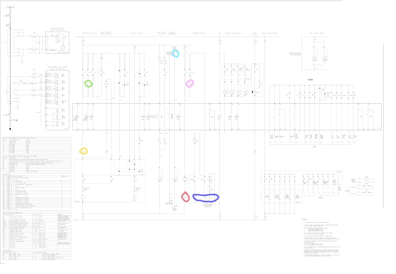
I understand that you need them to isolate tripping functions, but what would be the reason why you would want to isolate certain trip functions? Looking at attached circuit breaker DC schematic example:
LK10 (light blue) BUS ZONE TRIP ISOLATION - I assume you need to remove this link if you are performing maintenance/testing on busbar protection relay when CB is closed so testing does not trip the breaker?
LK17 (green) and LK18 (turquoise) BUSBAR PROTECTION TRIP ISOLATION and BUSBAR PROTECTION INTERTRIP ISOLATION - why do you need these links when you can isolate busbar protection trip relay via LINK10 (light blue)?
LK4 (orange) TRIP ISOLATION LINK - what would be the scenario/reason when you would have to remove this link?
LK12 (red) INTERTRIP RELAY SUPPLY - what would be the scenario/reason when you would have to remove this link?
LK13 - LK16 (blue) INTERTRIP PILOT ISOLATION - what would be the scenario/reason when you would have to remove this link?