Continue to Site

Eng-Tips is the largest engineering community on the Internet

Intelligent Work Forums for Engineering Professionals

  • Congratulations waross on being selected by the Eng-Tips community for having the most helpful posts in the forums last week. Way to Go!

Can this machine's SCCR be determined with this diagram?

Status
Not open for further replies.

jenggt

Industrial
Aug 10, 2023
2
Hello all, I am in the midst of getting a new grinding machine and I need to determine the SCCR. I'm hoping I don't have to purchase a UL field evaluation and thank you all for your help in advance.

The machine is wired to 220/3/60. This is the schematic I received when requesting the fault rating/SCCR (I've also attached a PDF that's less blurry than the screenshot, still difficult to interpret):
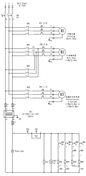
circuit_f7wdpa.png


This machine is imported from Taiwan so communicating with the factory and response time pains me on this. If they don't have the SCCR and it can't be solved, is there a better or different way of communicating the question to the factory to help me find the SCCR?


Josh - Machine Tool Distributor
 
Replies continue below

Recommended for you

IEC 61439-1 provides some information on IEC Short-Circuit Current Strength. Not the same as NFPA 70 SCCR, but may be a defensible option.

This posting may be helpful as the question may need to be asked differently.
I should have stated this when I made this post - USE of the IEC number similar to SCCR in it's place is not technicality sound, and is unlikely to be accepted by an AHJ that is paying the issue attention.
 
No. You need the ratings of each component. If they aren't all UL listed then you're dead in the water.

For that diagram, it'd be the lowest fault rating of all the components excluding the transformer and the transformer secondary stuff.
 
Can this machine's SCCR be determined with this diagram?
Quick and honest answer:
NO
The drawing is too blurry and the .pdf cannot be found.

--------------------
Ohm's law
Not just a good idea;
It's the LAW!
 

Whoops. There's a link now. Yes, it's blurry that's how I received it unfortunately. I'll reword the question by saying if I can determine all the values of the schematic would it be possible? It seems from previous replies that it's not.
 
jenggt (Industrial)(OP)10 Aug 23 17:40
"... I am in the midst of getting a new grinding machine and I need to determine the SCCR. I'm hoping I don't have to purchase a UL field evaluation..."
1. In the US, take the learned advice of Mr. LionelHutz (Electrical)11 Aug 23 12:28
No. You need the ratings of each component. If they aren't all UL listed then you're dead in the water.
2. Even ALL components are UL listed, there are numerous problems to put a SCCR on the panel, which is a mandatory in the US.
3. I am proposing the following for your consideration:
a) Assuming that the SCC at the point is < 10kA, then you can add 10kA MCB ahead of KM1, (KM2+KM3) and KM4 respectively. In this way, the board SCCR is limited to 10kA.
b) The control transformer secondary non-fused line shall be grounded.
c) The TR1, TR2 and TR3 N.C. contact shall be placed on the fused line i.e. NOT on the non-fused line.
Che Kuan Yau (Singapore)


a) Assuming that the SCC at the point is < 10kA, then you can add 10kA MCB ahead of KM1, (KM2+KM3) and KM4 respectively. In this way, the board SCCR is limited to 10kA.

That's not how you make a 10kA SCCR panel.
 
At one point in time it was common to use current limiting fuses to solve inadequate SCCR problems. Under current rules that is now technically unsound.

Adding line impedance or an isolation transformer can solve the excess available fault current, but you need to verify by calculation.
 
c) The TR1, TR2 and TR3 N.C. contact shall be placed on the fused line i.e. NOT on the non-fused line.
WRONG

Did you mean FR1, FR2, and FR4?
Those are the contacts on the overload relays.
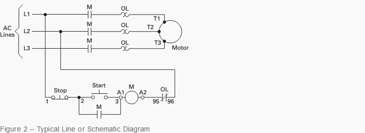
When I first encountered standard motor control diagrams, over 50 years ago, even very old texts and Motor Wiring Diagram Books placed those contacts exactly where they are shown in the diagram.
It has to do with the factory construction and factory wiring of magnetic motor starters dating back for much longer than 50 years.
In the early years, line voltage control was common for magnetic motor starters.
Screenshot_2023-08-15_at_18-21-29_Basic_wiring_for_motor_control_-_Technical_data_guide_EEP_gtvbhw.png

The jumper from the sealing contacts "M" to the coil, "3" or "A1" was factory installed.
The jumper from terminal "A2" on the coil to terminal "95" on the Overload contacts was factory installed.
The jumper from terminal "96" on the overload contacts to line 2 was factory installed

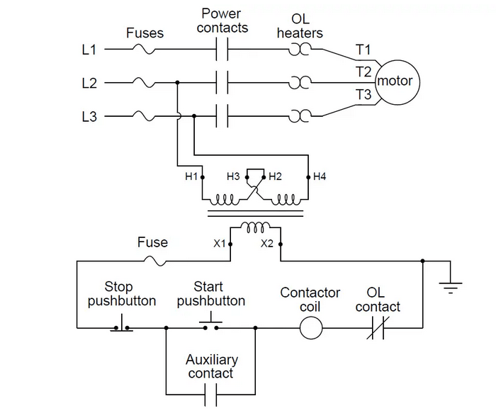
The industry trend has been away from line voltage control to separate control sources.
This is a typical modern wiring diagram:
Screenshot_2023-08-15_at_18-33-24_Motor_Control_Circuit_Wiring_wjaizi.png

The original wiring diagram has been replaced with this diagram, and the connection of the overload relay in the grounded circuit conductor remains.
The internal jumpers are still factory pre-wired.


--------------------
Ohm's law
Not just a good idea;
It's the LAW!
 
@ Mr. LionelHutz (Electrical)14 Aug 23 12:13
Quote:
That's not how you make a 10kA SCCR panel.
Agreed, there are numerous factors to be taken into consideration.
My reasoning is as following. Your advice are welcome.
1. In the US every panel shall be marked with SCCR in(kA) and operation voltage in (V). The panel builder is responsible for the [UL listed] components selection and "justify" the SCCR he claims. Note: it would be too costly to UL test the one-off small panel.
2. The present circuit shows no [short-circuit] protection. Note: The contactors and the (thermal over-loads <1A) would withstand say about 200A 1s. That is, the SCCR would be very low.
3. The SCCR of the panel shall be > than the SCC level at the point of installation. What is the SCC level at the point, is to be calculated by the plant's consultant, which is not within the responsivity of the panel builder.
4. If 10kA MCBs of appropriate current rating are added ahead of the starter, it would protect the contactor+thermal over-load, in case of a short-circuit < 10kA. Note: a 10kA MCB would reduce the Ipeck to say < 3kA within say 0.01s.
5. With the 10kA MCB, the panel may? claim SCCR 10kA at 220V; that is suitable for any location with SCC level <10kA. Note: this would fulfil that no danger to the operator or property in case of a short-circuit < 10kA at any location with SCC level < 10kA.
Che Kuan Yau (Singapore)


in question.
2. The
 
@ Mr. waross (Electrical)16 Aug 23 00:39
Quote:
c) The TR1, TR2 and TR3 N.C. contact shall be placed on the fused line i.e. NOT on the non-fused line. WRONG.. Did you mean FR1, FR2, and FR4? Those are the contacts on the overload relays.
1. Thank you Mr. waross. You are RIGHT. I mean FR1, FR2, and FR4,the N.C. contacts on the overload relays. The drawing was unfortunately rather blur.
2. Your second schematic showing the OL N.C. contact with one end connected to the contactor coil and the other end to the grounded line is WRONG. This is equivalent to switching the grounded neutral.
3. A simple illustration would show the flaw:
a) with OL N.C. contact placed after the contactor coil with terminal say a and b, when b is shorted to ground; the contactor would remain energized during OL. This is unacceptable!
b) with OL N.C contact placed before the contactor coil, the OL would trip the system even the coil terminal b is grounded.
Che Kuan Yau (Singapore)

 
My reasoning is as following. Your advice are welcome.

No, you don't do that. There is a panel building standard and UL has what they call the 508A Industrial Control Panel Shop Program which together tells you how to build a panel to achieve the SCCR you want then allows you to put a UL label on the final product.

You're talking about a current limiting breaker, I think.

 
It is obvious that you have zero North American experience, Mr. Che.
My diagram shows what has been the standard, pre-wired North American standard for Magnetic Motor Starters for at least 80 years.
It is a universal convention.

--------------------
Ohm's law
Not just a good idea;
It's the LAW!
 
@ Mr. waross (Electrical)16 Aug 23 18:16
"....It is obvious that you have zero North American experience, Mr. Che My diagram shows what has been the standard, pre-wired North American standard for Magnetic Motor Starters for at least 80 years.... ".
My opinion is : Your second schematic showing the OL N.C. contact with one end connected to the contactor coil and the other end to the grounded line is WRONG..... with OL N.C. contact placed after the contactor coil with terminal say a and b, when b is shorted to ground; the contactor would remain energized during OL. This is unacceptable!
Your learned advice on the "opinion" is welcome. It is irrelevant whether it is the standard practice for at least 80 years.
Che Kuan Yau (Singapore)
 
Allen-Bradley was founded 120 years ago, initially building compression rheostats for motor speed control. (Carbon Pile Rheostats)
1934 – The first solenoid starter with a single moving part creates a sensation. Allen-Bradleys first Magnetic Motor starter?
Allen-Bradley Wiring Diagrams
I have included a link to a booklet published by Allen-Bradley for the use of designers, engineers, electricians and others showing standard starter wiring schemes.
Similar booklets have been published by;
Westinghouse
Furnace
GE
Square D
And by any other major North American manufacturer of magnetic motor starters.
All show similar wiring schemes.
When I was writing and teaching industrial motor control courses, I had multiple copies of all of the various booklets that were available for both my use but mostly for student use.
What a wonderful hubris.
All of the North American manufacturers, all of the North American industrial electricians, all of the North American engineers, all of the North American panel builders, and myself, for probably 70 or 80 years, all of us are wrong.
Congratulations on being the only one out of many millions who is right.
coil with terminal say a and b, when b is shorted to ground
Yes, but we are concerned with a jumper from the coil to the O/L relay, typically not exposed to any external damage.
In many cases this jumper is less than 3 inches long.
In many many years grounding of this jumper has never been a problem.
And yes, as in all things, there may be the odd exception.
The German firm, Klockner-Moeller is an exception. Klockner-Moeller does not wire the overload relay in the grounded conductor.
Of course, they prewire their equipment to their own scheme.
Are they, wrong?
No, just different.
We are happy to use their equipment, but first time users are often confused until they realize that K-M follows a different standard.

Why do I bother arguing?
Most of the experts here don't care enough to become involved.
However, for those who have been diverted from their comfort zone to an application that may not be familiar to them, clarification is in order.

--------------------
Ohm's law
Not just a good idea;
It's the LAW!
 
Mr. waross (Electrical)17 Aug 23 00:3
1. I am a septuagenarian, we do not practice the NEC in this location.
2. I recall some years back that in the US and Canada, where it is the standard practice for LV three-phase motor having OL relays having only two heater elements, connected to a Y transformer with neutral grounded system. This WRONG practice must had persisted for many years. Now the Code is insisting that a three-phase motor connected to a Y transformer with neutral grounded, shall be with THREE heaters.
3. If some practice which is WRONG, it should be corrected; no matter how many years it had been "mistaken" as the standard practice.
Che Kuan Yau (Singapore)
 
"2. I recall some years back"
Yes, as I recall, over 60 years back.
The issue had nothing to do with transformer connections.
It had to do with unequal phase to phase voltages and phase angle errors.
Both line to line voltage inequalities and phase angle errors are common when field mounted voltage regulators correct unbalanced line to neutral voltages on distribution circuits.

The issue did cause motor burnouts.
The issue was noted.
The issue was corrected by the addition of a third overload element.
We still see motors overheating as a result of unbalanced line to line voltages and phase angle errors, but the motors are now properly protected.

The connection to which you so vigorously object has not caused any issues.

The codes in North America are developed by representatives from industry.
Committee members include.
Inspectors.
Fire marshals.
Industrial maintenance supervisors.
Wiring Manufacturers.
Equipment Manufacturers.
Contractors, Installers.
Insurance representatives.
If there is a recurring issue it is addressed.
One issue has been overloaded neutral due to harmonics developed by lighting ballasts.
That was identified and addressed many years ago.
More recently the issue of overheating neutrals has become worse with the proliferation of switching power supplies.
That was identified and addressed.
I repeat, there is no issue with the prevailing wiring methods.
In the years that I have been participating on Eng-Tips I have come to realize that there are different standards around the world.
Things that are legal and right in Europe may be illegal and wrong in North America.
To put things into perspective;
The US is the third largest country in the world.
Canada is the second largest country in the world.
In that area, you are anticipating a problem that does not exist.
It is wrong of you to tell someone that a circuit (apart from SCCR issues) is accepted by all of the code bodies having jurisdiction is wrong.
Time for you to apologize and shut up.


--------------------
Ohm's law
Not just a good idea;
It's the LAW!
 
Status
Not open for further replies.

Part and Inventory Search

Sponsor