Eng-Tips is the largest engineering community on the Internet

Intelligent Work Forums for Engineering Professionals

Can this mechanism be further optimized with 2 small pneumatic cylinders instead of 1 big cylinder? 2

Status
Not open for further replies.

Imposter666

Mechanical
Jan 15, 2021
36
0
0
CA
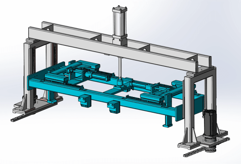
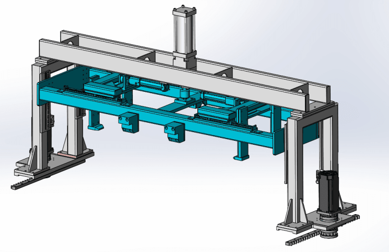
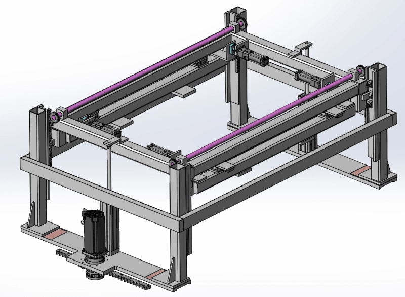
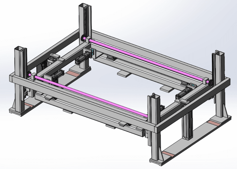
This lifter I have designed is lifting 100lb weight 300mm up from a surface and transferring it to another station. As you can see the the middle gripper is supported by LM guides at the ends. It is lifted by a single 80mm dia cylinder at the center. Originally I had 2 equal sized cylinders at each sides, but I was concerned that if one cylinder moves slower due to deteriorated seal or something, it might cause jamming on the LM guides due to imbalance of forces. I am personally not a big fan of this single cylinder sticking out like an antenna in the middle. I was wondering if there is a way to make 2 small side cylinder work instead of this big center cylinder.

1_xpyxik.png
2_hkjdas.png
 
Replies continue below

Recommended for you

That type of guiding will generally not work well, whether one or two cylinders. You should mechanically synchronize both ends with rack and pinion or cable and pulleys. If level movement is not important, use two speed-controlled cylinders without any guides to jam.
 
Not a fan either. You have a formula there for binding (and probable bearing damage) due to imbalance. The key here is that you have no mechanism to guarantee that the motion on both sides is equal, even if unevenly loaded. In the real world they will NEVER be equally loaded. Add in a little bit of extra friction on one side for whatever reason, and there you go. Bang.

There are a few methods to guarantee equal motion on each side but they aren't super simple.

How critical is it that the vertical motion actually be precise? Are you restricting yourself by using precision guided bearings on each side? Could you just as well use a couple relatively loose guide bushings on a couple of vertical guide rods, with a VERY loose fit?

I don't really have an objection to a central cylinder as opposed to twin cylinders. The problem isn't the location of the lifting force. The problem is the unequal vertical travel of those sides.

People overuse precision guides because they misunderstand them, and then they suffer consequences. Unless there is a good reason to use precision bearings, I would avoid them. Again, like I said, the problem is to guarantee equal vertical travel. All the precision bearings do is restrict any horizontal variation.
 
Jboggs and Compositepro,

I see what you guys are saying...The level of precision is not important. it can be +/-5mm. I will look into some alternative mechanism other than precision guides. Do you guys have any examples you can propose? an image or a sketch would be awesome!

 
A pair of racks and a shaft with pinions on each side works to keep things level without a lot of fuss. Similar is used for winding rolls of nonwoven sheet.
 
TheTick,

That's what I was looking at as well. Do you also share the same concern about the precision LM guides as the gents above? I was thinking to switch to simple rollers running on the flat surface of the sides as a replacement. A roller that has an in-out adjustability.
 
Do you even need linear bearings on each end? If the weldment is consistent from piece to piece then there would be a consistent gap on each end keeping the the weldment from tipping too much. Maybe you need precise alignment for what you are doing?

If you went with two double ended cylinders and piped the two cylinders in series then the same amount of oil would flow in each (other than leakage and oil compressibility).
 
It appears this machine is going to see many cycles per day. It would be wise to put some effort into design to create a structure that resists wear. Do use bearings.
 
If you need the overhead clearance, you could design a lever mechanism and place the cylinder horizontally.
That would also allow you to duplicate the levers on both ends and do away with guides if you wanted to.

= = = = = = = = = = = = = = = = = = = =
P.E. Metallurgy, consulting work welcomed
 
A pair of lead screws or ball screws connected with a cogged belt could also achieve a synchronized lift. These be powered with an air motor which would eliminate the need to make any changes to your control system if it is already designed for a cylinder.
 
Where is the center-of-gravity relative to cylinder?

What does a section through the gibbs/vertical slides look like - are these LM linear bearings?

If linear bearings, the frame weldment needs to be too precise, or else an induced load is created while trying to pull the framework to match the parallelism requirements of the bearings. Think about using something less precise - maybe one LM bearing /rail and the rest non-competing cam followers, or yoke rollers, or slide plates.

If there is an alignment coupling at the end of cylinder rod, it should handle maybe .060" parallel misalignment, if the cylinder mount is not perpendicular to the linear bearings, most of the misalignment could be used to accommodate the cylinder misalignment and you could end up with seal wear. So, if it is not necessary to exert a downward force with the cylinder, then a pivot link might provide for more misalignment.

Speaking of cylinder, if this is a pneumatic cylinder, it may get away from you when you go to push it down, since you most likely won't be providing any counterpressure to lower the load - i.e., the pressure will be applied at the cap end, and not the rod end.

 
Here is my preferred method for synchronizing motion on two ends of a load. Its similar to the connected hoists above.
synchronized_lift_acnugk.png


In this manner, the motion of both ends of the load is tied directly to the position of the common shaft above. The only variation in their relative positions will be from the torsional deflection of the shaft.

You could drive the shaft (with electric or air motors), or you could leave the shaft unpowered, and just use it to synchronize the motion of the ends. You could even attach an air cylinder to only one end of the load. That end cannot move without causing the other end to move with it. So the position of the driving force becomes irrelevant.
 
Thank you everyone for your insights. I have come up with a mechanism that should alleviate the concerns listed by you. I will change the design in coming days and post it here for further review.
Thank you!!
 
Thank you all for your input. I changed the design quite a bit. Please keep in mind that this is still in draft stage. I have 2 cylinders on each side lifting the middle section. I have 2 link shafts with gears attached to them. They synchronize the movement on the left and right side. I also replaced linear guides to cam followers with eccentric shafts. Eccentric cam followers will allow the mechanism to fine tuned to a certain degree but will still have more 'give' than lm guides hence less likely to jam. Let me know what you think of this mechanism.

4_llngoh.png
5_yatcrz.png
3_ymxxnp.png
 
Status
Not open for further replies.
Back
Top