Continue to Site

Eng-Tips is the largest engineering community on the Internet

Intelligent Work Forums for Engineering Professionals

  • Congratulations SSS148 on being selected by the Eng-Tips community for having the most helpful posts in the forums last week. Way to Go!

Can you do strength calculation on these weld

Status
Not open for further replies.

Verkstad

Mechanical
May 17, 2011
44
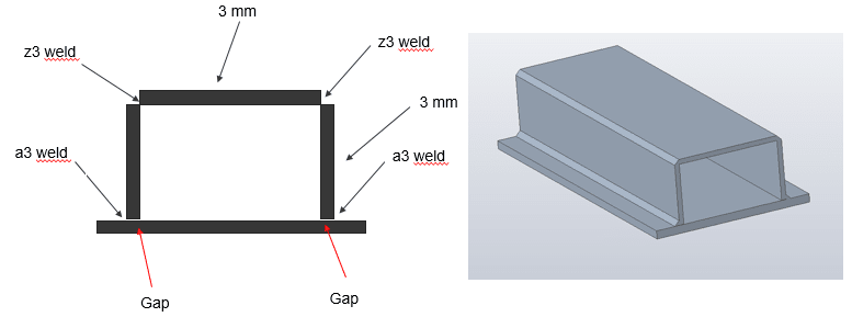
One of our engineers claims that you can not calculate do on these welds (the a3 and z3 weld in the picture).
Because the weld will not be X-rayed as a result there can be crack starters in these welds. He says that you need 3 things
to do calculations on these weld 1. Material data 2. Load on the weld 3. information on where
the imperfection are and it’s geometry. Is that statement true and if it is not how do i motivate that?
These structures are subjected to low forces, you have a high safety factor.

Bild_2_ytjnvv.png
 
Replies continue below

Recommended for you

Hi Verkstad

Yes the statement is true, without material data and a value of forces and direction you cannot do any calculations that tell you the welds are satisfactory. You do not always need to know where imperfections lie within a fillet weld because the usual theory and calculations usually allow for imperfections in the safety factor particularly if you are following a code like ASME etc.
Fillet weld normally fail across the weld throat as a result of shear stress within the weld.

“Do not worry about your problems with mathematics, I assure you mine are far greater.” Albert Einstein
 
The only thing i do not have is information on the geometry of the imperfection. Which means that you can do calculation on this weld according to this statement. The weld will be done according to ISO 5817. I can also change the design to get a even higher safety factor if needed. If you do not follow a code like ASME how do you take imperfection in to the safety factor then? The reason i ask is that i need to motivate that you can do calculations on these two welds.
 
The factors are normally built into the calculations themselves however you are working to ISO 5817 which should give safety factors on the materials in use, have a look at this website it shows the basic calculations for weld strengths


“Do not worry about your problems with mathematics, I assure you mine are far greater.” Albert Einstein
 
Verkstad said:
The only thing i do not have is information on the geometry of the imperfection. Which means that you can do calculation on this weld according to this statement. The weld will be done according to ISO 5817. I can also change the design to get a even higher safety factor if needed. If you do not follow a code like ASME how do you take imperfection in to the safety factor then? The reason i ask is that i need to motivate that you can do calculations on these two welds.

Have engineering show a close-up of the weld cross-section on the drawing and/or FEA analysis. Then show those to the welder / weld engineer, and have them comment on the differences. The functional difference is usually in the root of the weld.

Also, conservative assumptions can cover lack of direct data. If the design is conservative, this works. I've worked with a variety of analysts in my career and frankly, some of them don't understand the real world well enough to leverage that solution. This breaks their brain. Or it attacks their perceived value to consider that one of the inputs to their highly academic and involved calculation limits the output to one significant figure.
 
Were you and the engineer discussing static loads or possible fatigue, and were ANY specific loads mentioned? FX, FY, FZ? internal pressure? Accelleration with the base plate bonded to the hull of Elon Musk's Starship ?

Any mention what constitutes a failure? The slightest permanent deformation ? breakage?

I think the loading would change that conversation a lot.

Some would say carefully done FEA is to determine the LOAD on the welds, but then the allowable weld stresses are best taken from a source like AWS D1.1, etc.
 
 https://files.engineering.com/getfile.aspx?folder=4968a953-741d-4206-9de0-9622888dd9f3&file=eng_tips_weld_strength_.png
I would have thought it would be very easy, but you need to know the loading. If not, then you can calculate the maximum shears based on either the section capacity or the flexural capacity. Using these shear values, it's easy to calculate the shear stresses.

Rather than think climate change and the corona virus as science, think of it as the wrath of God. Do you feel any better?

-Dik
 
Verk....

Why do your two Z3 welds even exist ??? .... I am confused here

Why did you not simply use bent plate ??? .... Explain why this cheaper and simpler method is not an option for you

MJCronin
Sr. Process Engineer
 
Status
Not open for further replies.

Part and Inventory Search

Sponsor