Eng-Tips is the largest engineering community on the Internet

Intelligent Work Forums for Engineering Professionals

Can you flip an aluminum beam? 1

Status
Not open for further replies.

S.K.G

Structural
Jul 15, 2024
20
0
0
CA
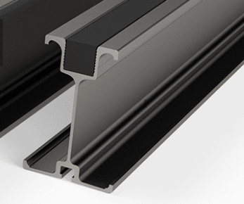
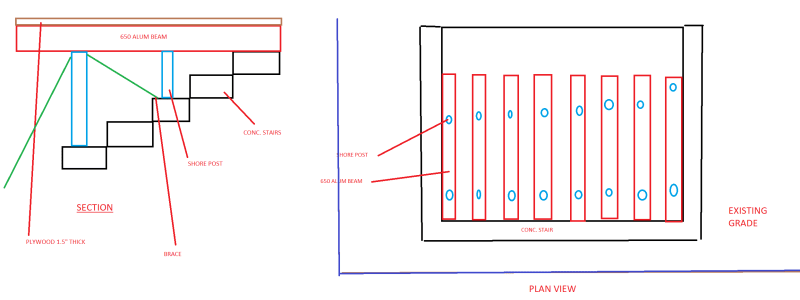
Are you allowed to flip an aluminum beam so that the bottom flange is at the top? I am currently designing a shoring platform that uses 650 aluminum beams. The top flange has a width of 3.5 inches and the bottom has a width of 4.8 inches. The beams have 1.5 inches of plywood on top (2 ply, 0.75 inches thick). The problem right now is that there is too much of a gap between the beams (the clear span) to where the plywood is unsupported for that clean span (currently about 9" clear span). This is a problem because the contractor wants to drive a heavy truck on top and the punching shear would likely be too high from the tire load and cause the plywood to fail. So I am proposing to flip the aluminum beam so that the bottom flange (width 4.8 inches) is on top and thus the clean span between each beam is small enough to allow the plywood to be unsupported only for a small length.
So my question is, are you allowed to flip the aluminum beam? My boss said he has never seen that done before. If so or if not, does anyone know of a reference where it might say it is okay or not okay?
 
Replies continue below

Recommended for you

This sounds like a structural question.
This beam is unsymetrical and the larger flange should be used for the higher stresses or lower allowables.
The beam does not care.
An architect may care.
What is the reason for this type of beam?
The Aluminum Association Design Guide may help you understand the allowables for each flange.
 
the difference in the flange width (1.3") makes that much difference to plywood decking ? Are you accounting for the increased flexibility of the wider flange ? Why not another sheet of plywood ?

But sure you can flip a beam, if you do the appropriate stress analysis ... smaller flange in compression may have a smaller compression allowable but may have a higher compression bending stress. I assume you're doing a linear bending analysis, what safety factor ?

"punching shear" ? affected by spans (ie bending) ?? How do the wheels of the truck match the spacing of the beams ? Can you align a beam under both sets of tires ? Maybe two ??

"Hoffen wir mal, dass alles gut geht !"
General Paulus, Nov 1942, outside Stalingrad after the launch of Operation Uranus.
 
Why does the beam have different flanges?

There may be a structural strength reason for that since they have different widths. Or the reason for the difference may be something different. Before answering if they can be "flipped" you need to know why they are unsymmetric.
 
Based on your limited description, this sounds like a proprietary aluminum extrusion used for concrete shoring, similar to those from Aluma, etc. - see below. If so, I am guessing you are using the manufacturers load charts, which should indicate the orientation, and I believe some manufacturers may have different values for use upside down. So I might check with the manufacturers. And for what's it worth, I believe that most of those charts are based on lateral bracing of the top flange from the connection of the plywood to the integrated nailer, which you wouldn't necessarily have.

Or, you could develop your own allowable stresses based on an appropriate aluminum design manual (in the US, the Aluminum Design Manual- ADM), including considering of the various buckling factors. This can be somewhat involved for complicated extrusions and requires a fair amount of information on the beam (including alloy/temper) that you may or may not have access to.

In my experience in situations where I needed to limit the joist spacing, I would generally try and adjust the shoring layout so I didn't lap the joists over a stringer (which is why I am guessing you have a 9" clear span). For example, if you have 21' long joists, you could use (3) bays at 7', and then butt the ends of the joists over double stringers at the supports. Though this can be challenging for the field and would require consistent joist lengths.

Or, a third layer of plywood per could also work.

Finally, I would be very careful about addressing any potential lateral loads. Shoring equipment is basically designed to support relatively static vertical loads only, and depending on your application, supplemental lateral bracing might be appropriate.


Screenshot_Aluma_Beam_tjetuq.png
 
If the beams are simple span, having the smaller flange on the bottom shouldn't affect the strength, since I and S are the same. However, if the beams are continuous over interior supports, the negative bending capacity over the supports may be severely affected, unless the bracing for the compression (bottom) flange is revised to account for the greater susceptibility to LTB.
 
I may be the same for both, but the state of stress (tension or compression) is flipped, and unsymmetrical beams have different extreme stresses. It is the same as if you flipped the sign of the moment.

i liked jjl's insights.

"Hoffen wir mal, dass alles gut geht !"
General Paulus, Nov 1942, outside Stalingrad after the launch of Operation Uranus.
 
I may be the same for both, but the state of stress (tension or compression) is flipped, and unsymmetrical beams have different extreme stresses. It is the same as if you flipped the sign of the moment.

Correct. The stresses in the flanges are reversed. I was thinking that the magnitude of the stresses in each flange would be the same, which I believe is correct, but the reversal of the stresses from tension to compression and from compression to tension introduces a couple other new considerations, besides LTB, that need to be addressed, namely flange local buckling, and fatigue.
 
Sorry I should be more clear in what I am talking about but your description is very close to what I am working on. I am using these aluminum beams from a company called HI-LITE. I have provided the specs for the 650 aluminum beam that I am using offered by them below. In the spec, they give the allowable bending moment for the top flange and bottom flange. I am assuming this means that I can operate the beam how I want but based on which flange is experiencing the load, I should use that flange's bending capacity correct? If so, does this mean that other reactions like the shear at the bottom of page 2 do not matter how you orientate the beam (smaller flange at top and bigger flange at bottom and vice versa)?
The reason I cannot move the beams closer or change anything else is that they have already assembled the shoring platform and would like a solution that does not require much work (they do not want to take apart all the shoring if they can avoid it). As a result of this, I need to check if the beams can handle the truckload that moves on top of them with the flange flipped to see if this solution works.
I am presenting a sketch of what the shoring looks like below (sorry sketch isn't the best, I did it in paint).

shoring_di5wdl.png


Basically, there is a depressed stairway here into the ground and they want to drive a truck over it which is why we are providing shoring (so the truck can drive on top safely).
 
good info and discussion by jjl317 and others.

I wouldn't flip the beam. There is a nailing strip on the top of these beams for fastening down the plywood. If you flip the beam you won't have anything to secure the plywood to.
 
While I recognize that it is a just a rough sketch, is there another row of joists not shown in your plan? You mentioned that you had a 9" clear span on the plywood - if so, isn't there enough room to add a joist added in the normal orientation?

If you want to pursue the upside-down option, I recommend reaching out to Hi-Lite for confirmation on your questions. And you may want to run through with them what you are trying to do, as they may have some thoughts, specifically on the safety factor, which is listed as 2.2:1 (which is probably appropriate for concrete shoring, but perhaps not for an application like this). And remember that there is a good chance that these beams came out of a rental yard and have been used/abused for years.

Regardless, based on the limited information provided, I can say that I am not a fan of this approach. When I have had to address localized wheel loads, it almost always involved layers of lumber and plywood, to distribute the point loads, and hopefully provide some redundancy. Plus, I would question the ability to provide adequate lateral bracing to independent shoring posts.
 
@jkl317
Thanks for your input, will look to call them.
What do mean another row of joists? There are 11 beams right now which are about 11-12 inch on center with a clear span of 9 inches with the 3.5 inches flange in top. If we flip the beams then there will be a clear span of about 7.5 inches. Based on my model of the shoring, the contractor should be able to fit additional beams in between the current layout basically doubling the amount of beams with about a 1 inch clean span but the contractor says they can't fit it. I am assuming the inch clear span isn't large enough for them.
And yes I agree I would like to add more layers of plywood and more beams personally but I am trying to figure out a designed based on what the contractor is willing to do right now. If I can prove that the current design is not feasible then yes I can tell my boss that the contractor has to re do the shoring.
 
The 650 beam has a 4.8" wide bottom flange, and they are 11" on center, you should be able to fit another one in (essentially at 5.5" on center) - basically add (10) more joists) - new total = (21).

Or maybe I have mis-understood you from the beginning - are you proposing turning all of the joists upside down, to reduce the plywood span? And if so, would that require a bunch of re-work? Or are you proposing adding (1) upside down joist in between two right-side up joists?

I'd bet $1 that they haven't given you the real story - I would recommend asking for photos - been down this road many times.

 
@jjl317
I am proposing turning all the joists upside down to reduce the plywood span. Currently the shorter flange is on top but I want to flip the joist so the bottom flange is on top. This would decrease the plywood span as I don't feel comfortable with a 9 inch unsupported plywood span having a heavy truck go over it. This would be the easist option for them which is why I need to check it. If it doesnt work then they will have to take out all the shoring and redo it so that the beams can be closer together. They are saying they can't fit an extra joist in-between each joist as I already did a design for that so now I need to check this new option. And yea I'm trying the get some more info (just a new EIT right now haha)
 
You have the problem that this wider flange not only puts a larger bending load on the flange, which looks to have a thin section, it also puts a larger twist on the beam. If the plywood is too flexible to bridge the gap it will simply dump those loads onto the flange.

If the floor is stiff enough then flipping the beam over won't be required.
 
I would not flip the beam.
This beam shape would drive you nuts determining the allowable and actual stresses in each component.

It is intended to be used one way and if it fails you are left high and dry all on you own, an island amongst lawyers.
"I don't feel comfortable with a 9 inch unsupported plywood span having a heavy truck go over it"
Why not?
Have you run the numbers?
You think 1 1/2" of plywood will fail when the tires whose footprint is probably at least 6" long rolls over it?
What are your loads?
How long will this be there with trucks rolling on it (1-week is a lot different thatn 8-months)?
Can you use steel plate instead of plywood and would that make yourself feel bettter?
Can you use a better grade of wood?
How is the plywood being fastened to the beams, it looks like the weak axis bracing is by wood that slips into the top flange cavity and gets fastened to the plywood...
 
Yea I ran the numbers and because of the small contact area of the tires, the plywood technically fails which is why I would like to keep the span to about 5 inches. The tire contact area is 20 in wide x 10 in long which I referenced from AASHTO. We can't use a steel plate of that size it would be too expensive I'm pretty sure. I honestly think they haven't even fastened the plywood and simply put it on top of the beams. The truck is simply moving across it like for a week, it won't be sitting on it or anything.
 
"We can't use a steel plate of that size it would be too expensive I'm pretty sure"
You are not sure?
1/4" steel plate is cheap and it does not change anything else.
1" road plate is cheap and may be readily available.

Does the plywood fail in deflection?
In which case, who cares?
Can you add another layer of wood or put one steel plate with the plywood?
Can you get better plywood?

You are doing a great job - "check this out" which you have done and it does not work or makes you uncomfortable.
Go with your gut, find a solution within the parameters you are given.
If they don't like your answer I bet either the paramaters will change or they will take your suggestion.

 
Have you checked everything in the load path from flange tip to support? Thin flange which is also bent twice doesn't look up to it and the Web is just as bad. Also you need to specify whatever lateral and twist restraint is needed. Haven't done any numbers but looks to me like the plywood needs to span to the beam webs not just to the flanges.
 
"I honestly think they haven't even fastened the plywood and simply put it on top of the beams."

This may not fly - the beams may roll or bend sideways without weak axis bracing, the posts may fall over.
 
Status
Not open for further replies.
Back
Top