Continue to Site

Eng-Tips is the largest engineering community on the Internet

Intelligent Work Forums for Engineering Professionals

  • Congratulations KootK on being selected by the Eng-Tips community for having the most helpful posts in the forums last week. Way to Go!

Can you solve the Rigid Plate on Springs Puzzle? 4

Status
Not open for further replies.

cal91

Structural
Apr 18, 2016
294
I'm designing hoisting/rigging/spreader bars for picking these large modules. They give me the attachment points to the modules and where the center of gravity is. So I just need to figure out how much force is going into each pick point. Theres are large modules with 12 pick points each, and I made a spreadsheet to find the forces at each pick point. It's set up similar to a rigid diaphragm distributing shear force to vertical elements, but it's got added complexity of being two dimensional instead of 1 dimensional. Balancing the moments in the two directions interact with each other and I'm trying to figure out how to set it up correctly so that summing the moments in both directions equals zero.

I simplified the problem into this little puzzle. I'm laughing at myself because at first glance this seems so easy to solve but I'm struggling.

See if you can solve it. I know I'm having a brain fart, but I'm gonna be stubborn and not come back on until I've solved it myself.
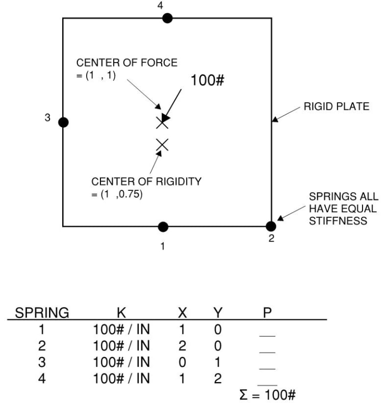
Rigid_Plate_Puzzle_beercx.jpg
 
Replies continue below

Recommended for you

I am probably mis-understanding your problem here, but ...

Plate is rigid, so its vertical deflection is given by
Z = A*X + B*Y + C
(where the plate is in the XY plane).
For any given (A,B,C) you can calculate all the spring forces.
You can therefore establish the three out-of-balance values, these being Z-displacement, X-rotation, and Y-rotation.[ ] All three should be zero.
Thus you have three unknowns and three equations to be satisfied.

Personally, I would set it up in Excel.[ ] Initially assume values for A,B,C.[ ] Calculate the three out-of-balance values, then calculate the sum of their squares.[ ] Use Excel's "Solver" add-in to find (A,B,C) that minimises that sum-of-squares.[ ] If that minimum is not very close to zero then something has gone horribly wrong.

 
I get:
1 = 2 = 18.18
3 = 27.27
4 = 36.36

ETA for typo
 
For reference - I looked at it like a bolt group to get an Ix about the neutral axis. Then the force at each spring is P/N + M*I/c.
 
I solved it via a system of 11 equations.

I used Denial's equation for a plane as 3 of the unknowns (A, B, C)
The other unknowns are 4 forces and 4 displacements, so 4 equations can be easily eliminated/substituted and I have 7 equations:

(1) F1 = KD1 = K(A+C)
(2) F2 = KD2 = K(2A+C)
(3) F3 = KD3 = K(B+C)
(4) F4 = KD4 = K((A+2B+C)

Sum moments and forces:
(5) F1 + F2 = F4
(6) F2 = F3
(7) F1 + F2 + F3 + F4 = 100

Substitute (6) into (3) and equate with (2) to get:
B=2A

Substitute for B in (3) and (4):
(8) F2 = F3 = K(2A+C)
(9) F4 = K(5A+C)

Substitute (1), (8), and (9) into (5) and (7):
(10) K(3A + 2C) = K(5A + C)
(11) K(10A + 4C) = 100

From (10), C=2A, substitute into (11):
A = 1/18
B = 2/18
C = 2/18

Plug A, B, C, and K=100 into equations (1) through (4):
F1 = 16.6667
F2 = 22.2222
F3 = 22.2222
F4 = 38.8889


Well done Denial and Aaron McD! I arrived at the same conclusion using the same method.


Azcats,
I was trying to use the method, P/N + M*x/Ix + M*y/Ix, but the problem is the M*X/Ix will have components in the y direction. The real world interpretation being, if you put a force directly on the Y axis, you will cause rotation about the X axis, and vice versa. So when you balance about your Y axis, you're screwing up you X-axis balance. This is what I was getting hung up on in the first place.

It is possible to solve using this method, but you first need to rotate your axes to the principle axes so that a force directly on the Y axis causes no rotation about the x axis, and vice versa.
 
BAretired said:
The solutions provided so far don't agree.

AaronMcD is correct. It balances all three equilibrium equations. Azcats has F and Mx balanced but My is not balanced.
 
Yeah - was editing my mistakes while you all were posting. Not doing great here on eng-tips today. [thumbsdown]
 
With slings having more than two legs and a rigid load, it is possible for some of the legs to take practically the full load while the others merely balance it. It is normal practice to assume the full load will be taken by two legs when designing the slings. Lifting studies are a bit of an art in themselves.
 
The puzzle aside, Retrograde is right for the practical answer. For a "rigid load" you need to design your rigging to take the full load in two legs (probably 1 and 4), and assume the others only provide stability. Especially if you have any sort of variability in your sling length (which you will, unless you have a load-rated adjuster in line, or a really slick rigging setup and a crane operator who's a pro with the whip line)

----
just call me Lo.
 
I love the creativity of getting the precise answer, but side (heavily) with @Retrograde's approach. Design load on the sling is minimum W/(n-1) and more than likely W/2 or W/3 per load. If these are big modules like pipe racks and industrial components: overdesign and safety are way more important than precise modelling. The COG will always find it's way right under the hook.
 
It seems overkill to have each cable/connection/spreader bar designed to carry half the load of the unit. We're taking care to ensure that the cables are the correct length such that the weight is distributed across all the cables.

Here's a youtube video of what we're hoisting.


Retrograde, Lomarandil and skeletron, (and any others) would you still assume each connection is carrying half the unit weight, or do you think my method is fine?
 
I would still assume that at least 2 of the legs aren't contributing directly to carrying the load of the module. Remember, you're not just dealing with pure gravity loading. You'll have wind, you'll have dynamic accelerations, etc. Sure, they may be small, but they'll be there. And rigging is not the place to cut corners.

Everything is overkill....until someone gets killed.
 
When I say cut corners I'm not implying you're trying to do something shady. Sorry about that. I mean it's no place to "sharpen your pencil."
 
cal91 said:
Retrograde, Lomarandil and skeletron, (and any others) would you still assume each connection is carrying half the unit weight, or do you think my method is fine?

One thing we know for sure is that the centre of gravity of the load in the video is directly under the crane hook. See below.

In the rigid plate illustrated in the OP, we know the location of the centre of gravity of load, but we do not know the location of the crane hook relative to the load. The center of rigidity shown on the sketch in the OP is not correct because the spring loads are not equal. In any case, the center of rigidity has no bearing on the problem. The plate will migrate to a position where the c.g. of load is directly under the point of suspension (the crane hook).

In an actual lift, the c.g. of load may not be precisely known, so the load distribution to the lift points cannot be precisely determined. For that reason, as well as the possibility of wind forces acting simultaneously, some conservatism and good engineering judgment is required.

SlingPuzzle_sbbyyc.png


BA
 
The idealised solution won’t match the actual loads. I’d design each point for half the load.

 
Alright, if you're talking about multi-level rigging with spreader bars, the problem changes somewhat. I would not design such a pick with 6-8 pick points as though each point carries 50% of the total unit, because if so, the spreaders would not be in equilibrium. Although I would not design them for 1/6 or 1/8 the load either.

Replies so far have mostly presumed multi-leg rigging connected to the same hook.

One other possibility is rigging with snatch blocks that force equal line loads (not equal vertical components). But that can often be more complicated than it's worth.

What rigging arrangement are you intending?

----
just call me Lo.
 
cal91 said:
We're taking care to ensure that the cables are the correct length such that the weight is distributed across all the cables.

If the actual cable length is only millimeters different from the theoretical this could have a large influence on the load distribution. In my part of the world, workplace health and safety regulations mandate that you consider the full load be taken by diagonally opposite legs (although this may not necessarily apply to multi-level rigging - the principal is the same though). I would be surprised if similar didn't apply to you.
 
Status
Not open for further replies.

Part and Inventory Search

Sponsor