Continue to Site

Eng-Tips is the largest engineering community on the Internet

Intelligent Work Forums for Engineering Professionals

  • Congratulations waross on being selected by the Eng-Tips community for having the most helpful posts in the forums last week. Way to Go!

CANTILEVER BEAM - CORBEL CONUNDRUM

Status
Not open for further replies.

Wazim86

Structural
Mar 29, 2021
5
Hi !

INTRODUCTION

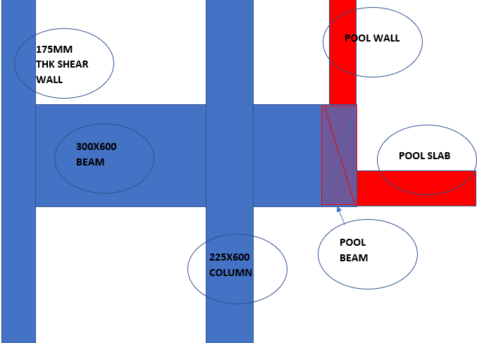
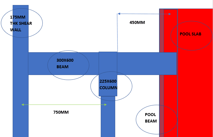
I'm forced to design a short cantilever, which has an equally short back-span. The c/s of the cantilever can be 300mm wide and 600mm deep. The cantilever is protruding out from a 225 x 600 RCC column, and also has a back span which connects to a continuous shear wall. The c/c distance between the shear wall and the column is 750mm and the cantilever length is about 500mm.

1. Now, the problem is this. The in-plane moment acting on the cantilever beam is negligible.
2. The axial load on the cantilever will be 380 kN at ULS.
3. There will be a significant torsional moment on the cantilever, which is 180kNm. This is transferred by the pool beam, which will be transferring 50% of the pool s/w , water load and live load. So this 180kNm would act as torsion, if im not mistaken.

QUESTION

1. Should I design this as a corbel, cantilever beam or a horizontal shear wall ?
2. Corbels are generally designed in such a way that the load transferring component transfers only forces, and rarely, moments. Not torsion in any case.

So, how do I tackle this problem?

Thank you.
 
Replies continue below

Recommended for you

1_yixeyy.png
2_tvf49z.png
 
I like this as mostly a cantilevered beam with some corbel nods thrown in where it counts for detailing. Somethings to sider:

1) Your pool slab will be somewhat of a "hanger" condition and will need to be detailed accordingly. No big deal.

2) Your pool beams will need to hit your cantilever at a "hanger" that will need to be detailed accordingly. Again, no big deal.

3) What maybe a big deal, as it is with corbels, will be end anchorage of your top steel in the cantilevered. This may be a good spot for a form of anchorage other than a standard hook. Maybe headed bar ends or dowels welding to transverse rebar etc. I'd be inclined to let corbel detailing guide my thinking on this.
 
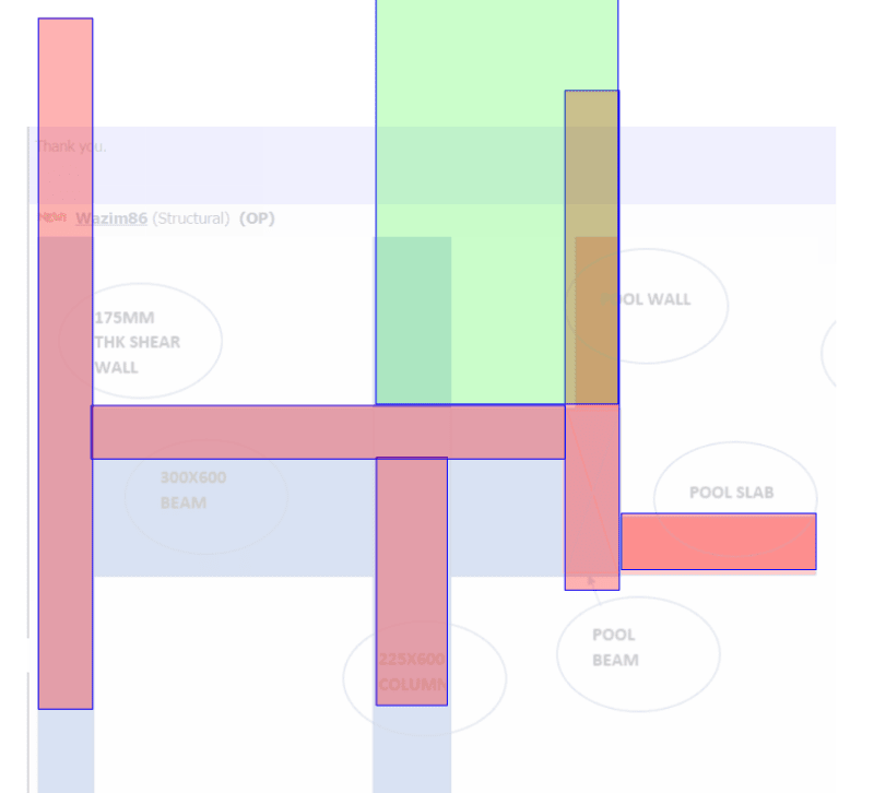
As an alternate solution, perhaps you could just enlarge the upper column such that it grabs the full height of the pool wall. What you've proposed is computationally doable but, at the same time, rather fragile in my opinion.

If you were to do this, you would first need to study the requirements of the pool detailing as it wraps the outer pool walls to ensure that this didn't cause problems there.

c01_pv640u.png
 
KootK

Thank you for your response. Totally agree about being fragile, it was actually a proposal by my senior. So I didn't have much of a day there, since he insisted on this.

My proposal was to have a corbel below the beam. However, citing issues related to aesthetics (it will be shown in the soffit of the preceding floor) ..he wanted me to design this.

As you'd recommended here, I too took the route of treating it like a cantilever beam - cum - corbel. This meant that I converted the Torsional moment in to shear and added Shear rf in the YZ plane. Then calculated Tensile force and provided main rf for corbel. Also provided stirrups in the XY plane, as per corbel calculations.

The whole thing looks like a meshed cube now. (Like a pile cap/deep beam) lol.
 
The alternative you've suggested is worth trying out, however, the space between the col and the pool might be used to drain water.
 
Wazim86 said:
This meant that I converted the Torsional moment in to shear and added Shear rf in the YZ plane.

Yeah... I've done similar things on occasion but I don't love this. In my mind there's not really a method available for designing a corbel for torsion that has been properly vetted via testing etc.

Wazim86 said:
The alternative you've suggested is worth trying out, however, the space between the col and the pool might be used to drain water.

Unless you're anticipating a Texas flash flood, you could just run a drainage opening through the column with some swales etc around it to encourage proper drainage.
 
With regard to torsion, there is more than one of these connections along the length of the pool, right?
 
I'm still getting used to this forum. Not sure how to quote or respond to a particular comment.

Anyway, yes, the POOL (ABCD) is basically supported by two adjacent supports (say AB
8m and DA 3.3m) that are stable and properly retrained without complications.

The dimension of the pool is around 7.6 m x 3.3 m.

Now the support CD (3.3 m long) is a secondary beam plugged in to BC and DA. BC again is a "floating beam" of sorts, which is plugged in to AB at a location adjacent to a column, and the other end is a cantilever. In the middle (say 2.2m from AB), it's supported on our corbel.

All beams are Upstand. Not visible to the floor below. Now the concern is the element BC. Pool is a one way slab. So majority of the load goes to AB and CD.

CD acts as a point load on BC.
THAT creates a moment of 180 kNm@ULS (My
for BC). There is negligible torsion moment on BC due to the pool.

The support reaction on the corbel is 380kN@ULS.

So these become the decisive forces acting on the corbel.

With respect to the corbel, Mx = 180kNm - a small wl2/12 of the internal span. So let's say the total out of balance moment is 150kNm.

The point load will create an My of 180kNm . (380*0.475)

So we are looking at V, Mx (basically Torsion) and My.
 
Status
Not open for further replies.

Part and Inventory Search

Sponsor