Continue to Site

Eng-Tips is the largest engineering community on the Internet

Intelligent Work Forums for Engineering Professionals

  • Congratulations KootK on being selected by the Eng-Tips community for having the most helpful posts in the forums last week. Way to Go!

Cantilever beam loading: 1 load on 2 beams

Status
Not open for further replies.

Lsos

Mechanical
May 15, 2011
11
Hello,

I have a situation with a cantilevered beam with a point vertical load AND a moment load. A combination of the two following scenarios:

plot_diagram.gif


plot_diagram.gif


I did the calculations, and basically the beam will fail. So I’m wondering what will happen if I put this load on 2 beams spaced vertically apart. Will the load get split evenly between the 2 beams? Will just the vertical load get split evenly, and the moment load get greatly reduced…or disappear altogether? Will the vertical load INCREASE? Do I need FEA analysis to figure this out? Does the vertical distance between the beams make a difference?

I have posted this on another forum and have gotten confusing responses including most of the above. My instinct tells me that the vertical load will be split amongst the beams, and the moment load will be greatly diminished depending on the vertical distance between the beams. But I’m not sure. Can anyone help me understand what’s going on?

Below is a diagram I made of my situation…basically a bolted joint with all the bolts loosened and removed, except for 2. The load is free to slide back and forth on the pins.

Thank you in advance…
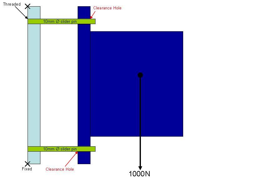
Diagram-1.jpg
 
Replies continue below

Recommended for you

the direct force (shear) is clearly 1/2d between the two beams.

the moment would get reacted as a couple in the two beams (th eupper one in tension, the lower compression); but there will be a smaller moment (in each) due to the shear load on each pin (moving the shear from the dk blue to the lt blue piece).

can you draw a free body diagram ?

 
the moment would get reacted as a couple in the two beams (th eupper one in tension, the lower compression);

That's the thing I was first thinking...but then how can the load put the bottom in compression and the top in tension, if it's free to slide on the pins?
 
ok, i'll buy that ... but what's to stop the dk blue piece from falling off the green pins ?

what's stopping the lower edge from displacing in, towards the lt blue support ?

if there truly is nothing for the dk blue to butt against, then it'll rotate CW till it binds on the pin.
 
Lsos,

Your structure with two pins is statically indeterminate. If all of your tolerances are exact, the two pins will be loated equally in shear.

Your structure provides no resistance to the horizontal forces. The blue thing will simply fall off. You need a spacer at the bottom, and a spacer and nut at the top.

Why can't you make your original cantilever bigger?

Critter.gif
JHG
 
whilst i'm sure there needs to be something to stop it falling off, i'm not certain that it is a certainty.

if the pins are very rigid they could react the applied moment with a tapering distributed load.

if the pins are flexible, they could bind in the clearance holes.

if here is a stop preventing the lower edge moving in, this could stop it falling off (and it'd rotate to bind on the upper pin, or fall off).

as drawn it does look very "odd" ... maybe add cross-bolt thru the pins to provide a loadpath for the moment, as a couple). maybe add nuts on the end of the pins ...
 
rb1957,

If both holes are accurate, the rotation required for the load to fall off, may be more than the rotation that will cause the pins to jam in the holes.

This does not sound like a good design strategy.

Critter.gif
JHG
 
quite agree; it might be, just not sure that it will be (as your 1st post said).

picking at words ... even if the clearance is very small, so that it does bind, it's a pretty "dumb" design as drawn.
 
Lsos:

This is really a pretty clean and simple problem, and if you are going to tackle it, you should probably dig out your first text books on Statics and Strength of Materials and study up a bit. You almost always retain what you learn on your own much longer than if you are spoon fed the same info. You should also be talking with and asking these questions of your boss or your senior engineer, right at work, so they know what you don’t know and can guide you properly to keep you and the company out of trouble. You have left a number of important dimensions off you drawing, which is another indication that you don’t really fully understand your problem. Given that, your sketch should at least be correct proportionally in terms of dimensional relationships, and sizes, etc.

As you’ve drawn it, you have an unstable system or design, which is potentially unsafe, never a good thing. The vertical load is basically split btwn. the two pins as long as they are the same size (stiffness), but because of the tolerance and manufacturing uncertainties mentioned above, one pin may be loaded before the other comes into play, so I’d probably design each pin for about 600N as a canti. load on the pin. Then, you don’t have a moment at the end of the pins, so much as a tensile force on the top pin and a compressive force on the bot. pin, and you must get these forces into the pins and back to the base pl. by some means. A slip joint at the pin will allow the load to just fall off the pins, onto someone. While you may have clearance holes for assembly, you must have a standoff with an 11mm I.D. btwn. your load flange and the base pl. and then a nut and washer on the pin, at the outside (right side) of the flange on the load. That pin tension will be approx. (1000N)(load C.G. to middle of base pl. lever arm)/(lever arm btwn. pins). It appears that you intend about a 60mm standoff, so you must size your pins to take the 600N at the resulting canti., or reduce the standoff length.
 
another observation from the pic ...
this is a section thru one set of attachment bolts, right ? ...
the total load applied is 2000N, supported by 4 bolts, right ??
 
A statically indeterminate problem; it is obvious that the loads on each pin will not be evenly divided and indeed, one pin could take the entire load leaving you with the same situation you started with.

I did some elementary statics and assuming one pin takes the whole load ( a real possibility)
WL=fx moment eq


2*mu*f>W

where
mu= static coefficient of friction
f= side thrust on pin forming couple
x= distance between couple

dividing, I get

mu>x/2L

which says that as long as mu>x/2L

it is possible that the load will be borne by one pin without slipping
 
First of all, thank you everyone for the help. I wasn’t expecting nearly this much this fast!

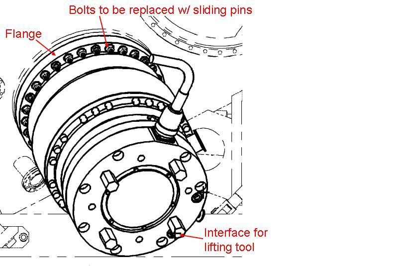
Let me explain a little better what's going on here. The "Blue thing" on the right is a ~100kg vacuum pump which is normally bolted onto the light blue flange on the left using something like 40 bolts.

Pump1.jpg


The issue, and this problem which I described, arises when we go to either remove or mount a pump onto this flange. There's a lifting tool which hangs off a crane, which you attach onto the pump to help you remove and mount it. However, this setup is not very stable and not very safe. One of the suggestions I got, indeed from a senior engineer, was to use these sliding pins to help stabilize the pump when moving it to/from the flange.

So while it does indeed appear to be a terrible design, it is only to be used very temporarily during mounting and removal, and all the while being attached to a lifting tool so that no matter what happens, it won’t fall. Nevertheless, it obviously makes sense to find out if the sliding pins can actually take the full weight of the pump. It also makes sense to figure out how many pins we need, how long they can be, etc.

The diagram above shows a cross section of the setup, using only 2 pins. Nothing is stopping us from using more pins, but I first wanted to figure out what’s going on when we use only 2.

Clearly I am unable to simply increase the diameter of the one pin as I am limited by the existing pump flange. I also cannot put a stop or a nut or whatever to take the horizontal loads, as the whole point of this setup is to be able to remove the pump, horizontally.

I also purposely omitted the exact dimensions or even explanation of what my diagram represents precisely so that I don’t get “spoon fed the same info”, but so that I can actually be helped to understand what is going on and go to solve it myself. The main thing that I got so far is that this is anything but a clean and simple problem which my Statics book will deal with, as it is not even statically determinate.

Whether the pump will simply slip and fall off, well ideally I’ll just add enough pins and/ or make them so short that they don’t flex enough to allow this to happen. How much and how many is what I’m trying to determine.

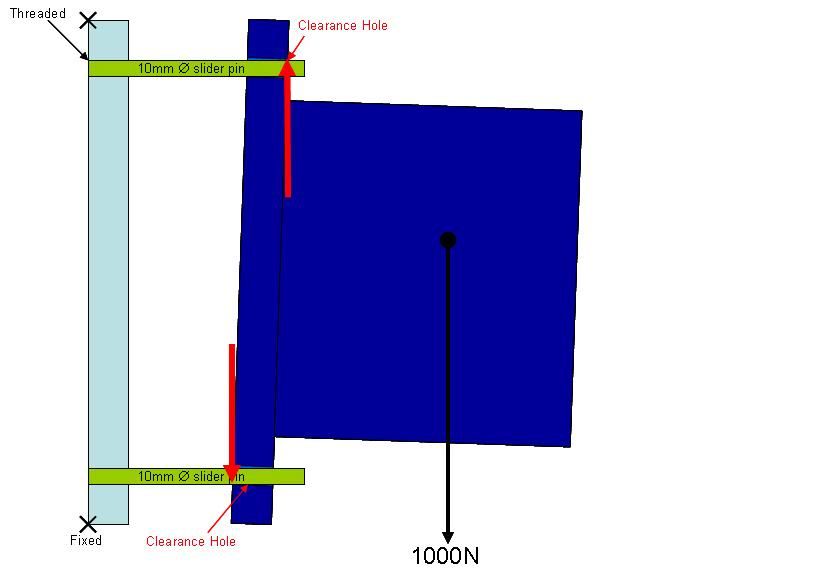
The question then remains: what keeps the pump from rotating? Do we get resulting forces as per the below diagram?

Diagram2.jpg


This looks to me as one sort of solution, but then this solution brings with itself some other problems. Is there simply too many variables to this problem to make it satisfactorily solvable using paper and pencil?
 
it doesn't make sense to replace all the bolts with clearance pins,
however, maybe you could replace 1/2 of them, use the bolt/nut for the service loads, and the clearance pins to restrain the item when you're removing it.
maybe just four pins ? widely spread around the flange ... probably wouldn't affect the service loads (in the remaining bolts).

as an option, maybe add a "catcher" flange under the item, something that is fixed in place.
 
I think that note "bolts to be replaced w/sliding pins" on the diagram clouded what I was trying to say. The intention IS to only replace maybe 2-4 of the bolts with pins, and even then only during mounting/removal...but certainly not all of them :)
 
Lsos,

Okay, so now this is a 3[ ]dimensional problem.

Statically, it will sit on the two pins. Perhaps they should be on the sides, rather than top and bottom.

Since this is a dynamic problem, I think you must assume that at some point, one pin must take the entire load in shear, plus something from the crane.

Is there any reason why you would disconnect your crane before your pump is pressed up against its mount? I would avoid cantilevering on the pins.

Critter.gif
JHG
 
Lsos:

Wow.... what a different and more complete and more detailed explanation of your problem. Now you might get some answers that really apply, without wasting our time guessing at what you want, or are doing wrong. This is not an indeterminate structural problem, so don’t complicate it further than needs be. It’s not a terrible design and concept, once you explain what you’re trying to do.

Aren’t you actually saying, ‘we need a few alignment pins to help guide this pump and its internal parts into final position so the bolt holes line up and we can start to put in the other 37 bolts?’ Your crane and pump holding device must be safe and reasonably stable, but otherwise for the last few inches of insertion or removal, you need some finer alignment help. Three pins, 120° apart will usually locate something pretty well, maybe at 12, 4 and 8 o’clock; where these three bolts are removed and your slide pins are installed. Now, your crane and holder device pick up the load, and the remaining bolts can be removed. Maybe some fine tuning on the lifting system is needed, and a longer chain above the pump will allow it to swing a few inches and still be pretty well aligned. Maybe this would be a finer operating chain fall below the crane hook. Certainly, the pump must be pretty well balanced on the holding device and hook.

Given what you’ve told us now, I don’t think the three pins are really loaded much at all. The pins could be loaded as cantilevers, as you observed, but you can’t get big enough pins in there to take this kind of loading. What canti. load will your 10mm pin take at 50mm and at 25mm without yielding? These forces must align the pump due to any imbalance on the hook, and your lifting system must work within the forces. Certainly the pins could be over loaded, but they’ll just bend and screw up the works. That’s why you must also look at the lifting system details. Very little force, by hand, by the men doing the alignment, must facilitate the fit-up and the pins are just there as fine tuning guides.
 
i think these should be permanent. to remove the item, you undo the nuts; i'm not sure you can back the studs out of the holes in the flange with the item in situ (in order to replace them with the clearence pins).

i would replace four bolts with sliding fit (very small clearance) pins (or dowels). undoing the bolts will cause the item to pivot about the contact point of the flange and the back-up structure, binding on the pins (so that the item doesn't fall off). the weight of the item is something like 10 - 20 lbs ? (not 100 - 200 lbs) so the loading on the pins shouldn't be excessive.
 
"There's a lifting tool which hangs off a crane, which you attach onto the pump to help you remove and mount it. However, this setup is not very stable and not very safe."


How about making a lifting device which will hold the pump safely & stably in the correct orientation for installation?

Alternatively if the pump casing is reasonably sturdy have a qualified rigger do the lifting using fabric slings.

Have you talked to your technicians about the task?
 
Thank you all for the suggestions and discussion. I didn't respond in a while as I was rolling everything over in my head.

I didn't inted to withhold information in order to "waste people's time guessing". I just wanted reduce the problem in its most basic and simplest form, so as to avoid writing an essay which would probably not have gotten read.

I would still like to be able to see how these things are loaded and what's the worst case they can take, just for sanity reasons. However, it is a good point that if that worst case happened, then some cheap pins would simply get bent but nobody and nothing would get hurt. It's not even certian that these pins will actually be made and/ or utilizd. However, they did present me with a problem which I, as an engineer, will feel incomplete until I can fully understand.

How about making a lifting device which will hold the pump safely & stably in the correct orientation for installation?

Our task was to design a tool that can remove the pump. We offered various solutions, including stiff and stable self-contained hoisting devices and frameworks. For various reasons including cost/ space/ weight/ and speed, our customer deemed that a crane-hung tool was most feasible.
 
Status
Not open for further replies.

Part and Inventory Search

Sponsor