Continue to Site

Eng-Tips is the largest engineering community on the Internet

Intelligent Work Forums for Engineering Professionals

  • Congratulations KootK on being selected by the Eng-Tips community for having the most helpful posts in the forums last week. Way to Go!

Cantilever retaining wall design 2

Status
Not open for further replies.

Kereo

Geotechnical
Dec 10, 2018
8
Hey everyone:

Trivial question here, but I asked my colleague and didn't get a convincing answer :(

So I've recently started designing a conventional cantilever retaining wall while working through the preliminary calcs, I became aware of the K(active) and K(passive) coefficients that I'm using. I mean, I've always been taught to use these coefficients to calculate the earth pressures acting on the wall. But will the retaining wall reach these limiting states, because according to Rankine, the wall has to undergo some degree of deformation before the K(At rest) reaches one of these limiting states.

I'm not sure whether this is more conservative, because when K(At rest) approaches K(active), the active pressure gradually reduces, so wouldn't it be more conservative to design the wall at a higher "K(active)" pressure? Why do we design the wall at its failure point?

Any advice would be greatly appreciated :) thx

 
Replies continue below

Recommended for you

"I would never assume that a sidewalk was supporting or even could support a retaining wall."

I wasn't assuming that the sidewalk would support the wall. I was assuming the sidewalk would restrain the wall from the movement necessary to relieve the at-rest pressure and reach the active pressure condition. If I designed it for Ka, it would likely rotate forward at the top to reach the Ka pressure condition, since it would not be able to slide because the bottom was not able to move. It would also put pressure on the sidewalk, which might cause the sidewalk to slide or crack.
 
Couldnt agree anymore with Hotrod, oldestguy and Fatdad really.

In my view designing for k0 earth pressures is a simple, conservative (but not unreasonably) so way of designing relatively stiff RC retaining walls e.g. bridge abutments (obviously more flexibile types are a completely different matter).

Also:

1. (Eurocode specific) - it saves a lot of the hassle of designing for DA1 C1/C2 particularly at the tender design stage.

2. You can only optimise the design so much (its really either B20s/25s/32's @ 150 centres - theres really only so much economy you're going to get out of using K0=0.33 vs 0.5 in a lot of cases for phi'=30, in a lot of instances you might allow a slight overstress by inspection to use a smaller bar diameter if its a very long wall.

3. We're to make a bit of cash at the end of the day
 
For the soil pressure on a bridge abutment, I would certainly agree with using Ko, at a minimum. If we have soil against our integral abutments, we design for the high end of the passive pressure to account for movement of the abutment into the soil.

We also do some fairly massive retaining walls supporting fill slopes for roadways. For those we use Ka and sometimes find it cost-effective to use select backfill rather than native fill. Although, on one recent project, the native fill was slightly better than our crusher run...

I can certainly appreciate your perspective of simplifying and shortening the design. I have a somewhat different financial setup, since I work for the agency responsible for paying for the construction (the DOT), so if I take the time to 'sharpen my pencil' and cut a significant amount out of the construction costs, the bosses like that. It's similar to designing for a design-build project. Also, it sounds like design for Ka comes with some extra headaches under the Eurocode; it's fairly straightforward under AASHTO. It's a long equation to calculate Ka, but once I had it programmed in Excel, it takes no time at all to use it again.
 
There may be reason for designing some walls and abutments for higher earth pressures, but Kereo's original question was about "designing a conventional cantilever retaining wall."

 
For the design of conventional retaining walls (unrestrained and which can move or rotate freely without significant impact on ancillary structures), I learned to use the following earth pressure coefficients:
- wall equilibrium (sliding and overturning): ka
- structural design of wall: (ka + k0)/2

As we aim for a stability safety factor larger than 1, it is foreseeable that the wall will sustain earth pressures larger than ka before it slides or rotates. In this way, we try to establish a failure hierarchy, guaranteeing that structural collapse won't occur before any stability issues.
 
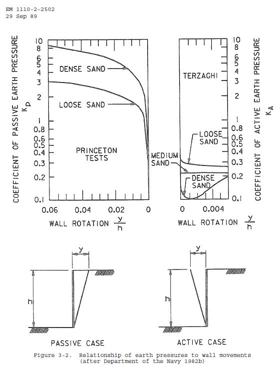
full passive pressure generally required only a very small movement (0.003 or less for half passive), so if you can stand any movement, you may be able to justify using it. For your 10 foot wall, that would be about 1/3 inch.

passive_movement_xwsmgq.jpg
 
avscorreia, AASHTO LRFD puts a load factor of 1.5 on lateral earth pressure for the structural design of flexible walls, probably for the reason you mentioned.
 
According to your graph as I read it, cvg, you don't get anywhere near full passive until 0.02*H, which for the case of the 10' (120") wall would be 2.4".
 
HotRod10, I forgot to mention: I use the Eurocodes so I use a 1.35 load factor on lateral earth pressure, so you're probably right regarding AASHTO LRFD.
 
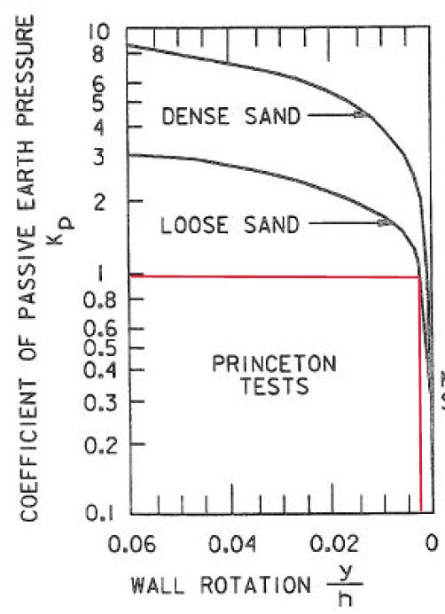
check again, you are misreading the graph. 1.0 Kp is at about .003 for loose sand and less for dense sand

passive_2_wfmgpf.jpg
 
What I considered "full" passive pressure for loose sand would be Kp = 3; half would be Kp = 1.5, corresponding to movement of nearly 0.01 ---> 1.2" for the 10' wall. It's similar for dense sand, with full passive being Kp = 8 and half being Kp = 4, crossing at a value slightly over 0.01.

From the AASHTO LRFD bridge design spec, Section C3.11.5.4: "The movement required to mobilize passive pressure is approximately 10.0 times as large as the movement needed to induce earth pressure to the active values. The movement required to mobilize full passive pressure in loose sand is approximately five percent of the height..."

Of course, that's only for sand. Mix in a little silt, clay, or larger granular material, and it changes considerably. From the same section: "For poorly compacted cohesive soils, the movement required to mobilize full passive pressure is larger than five percent of the height..."

In any case, I'd be hesitant to count on any amount of passive resistance on something where movement would be detrimental.
 
nobody is recommending that full passive pressure be used. corps of engineers and navfac recommend no more than .5kp and only if you cant achieve stability using at rest pressure or you have a deep structure. according to the chart, .5kp would require very little movement, about .001 or .002.
 
Well, I won't be hanging my hat on that supposition, especially since we rarely have clean sand as backfill material.
 
Eurocode (EC) 7 provides some very different numbers!

For 0.5kP, EC7 indicates 1.1 to 4% of wall height for loose to dense sand, 0.011 to 0.04 x H. Thats 10 times more than cvg's Department of Navy reference.

I am sure that both methods were developed based on retaining wall monitoring at some point in time, but my gut says that 0.001 to 0.002 x H for 0.5Kp is too small a movement! For a 10ft wall thats 1/8" to 2/8" or 3 - 6mm.

In saying that, that's just my gut feeling and i have never actually measured pressures in a retaining wall!

Its after sparking my interest so I may look into it a bit more and see what i can find. If anyone has any references, let me know.
 
EireChch, your Eurocode values are similar to what's in my soil mechanics textbook. Anyway, in the rare circumstance where we include passive resistance in a design, it's only used for sliding resistance, and the depth (Height) is generally 2' or less and we're counting on it to mobilize a wedge of soil in front of the wall. I can't see how any graph value or anything multiplied by the height would be applicable.

As I said, I won't be counting on any passive resistance for anything where the movement is, or needs to be, limited.
 
I’m with PEinc, been doing this a long time and have never designed a conventional retaining wall for an at-rest condition. I’ve only used at-rest for the design of foundations related to thrusts from arch type superstructures on bridges.
Soil Mechanics 101 will cover the design of a retaining wall. Of course if you do design for an at-rest condition it’s just conservative.
 
Again, deciding on at-rest or active pressure for design is not complicated - if an inch or so of movement of the wall will not cause problems, designing for active pressure is generally acceptable. If it makes for simpler design calculations or the designer wants to be conservative, using at-rest pressure will usually require a more substantial wall. For walls that are not very long, the cost difference may be negligible.

For walls, abutments, etc. where movement would be detrimental, or external restraint doesn't exist or isn't adequate for the forces, design for at-rest pressure is generally recommended and prudent.
 
"I don't see how designing for the at-rest condition is a simpler design."

Under the AASHTO code that I design to, it's a minimal difference. Calculating Ka is accomplished using a fairly large formula, but once I programmed into Excel, it takes no extra time now. I was referencing a comment by ukbridge, posted on Feb. 9th, indicating there were additional requirements to design for Ka under the Eurocode.
 
Whatever pressure is used, I hate leaning walls, so I want the front face to be built sloping back to the earth.
 
Status
Not open for further replies.

Part and Inventory Search

Sponsor