Continue to Site

Eng-Tips is the largest engineering community on the Internet

Intelligent Work Forums for Engineering Professionals

  • Congratulations SSS148 on being selected by the Eng-Tips community for having the most helpful posts in the forums last week. Way to Go!

Cantilever Sheet Pile Wall Design - Granular Soils 8

Status
Not open for further replies.

ChiEngr

Structural
Oct 19, 2021
77
Hi Everybody,

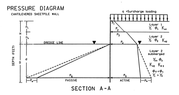
I have a general question with regards to cantilevered sheet pile wall analysis with Granular soils. I am able to easily perform the pressure analysis due to active and passive pressures on the wall when there is no surcharge. However, when surcharge is introduced I am a bit confused. Do I include the surcharge only as an active pressure on the wall? Or should I be multiplying the surcharge pressure by (Kp - Ka) if I am trying to determine the passive pressure acting on the wall? I guess my question is, in the attached image, how do I incorporate the surcharge in calculating P_J. It does not make sense to me to multiply that pressure by (Kp-Ka). I have looked endlessly through textbooks and online for examples of this situation, and I am shocked I have not found anything of the sort. Thanks in advance for your help!
 
 https://files.engineering.com/getfile.aspx?folder=6b3f0a4f-9149-443a-abcf-45807dfa88ab&file=SheetPile.png
Replies continue below

Recommended for you

In my designs, I have only considered the surcharge in the destabilizing forces. Realistically unless your surcharge is quite large, it doesn't really affect the design of the wall signficantly. Let's say your surcharge is 250 PSF and a Ka=0.5, doesn't take much for passive pressure to dwarf that at a soil density around 130 PCF and a Kp=2.0. for granular soils I'd expect your Ka to be lower still than 0.5 and your Kp higher than 2. So the effect of the surcharge is even less.
 
@jayrod12:

That makes sense to me; It does not make much sense to include the surcharge as a stabilizing pressure at the bottom of the wall.
 
As a simplification, can you just increase the wall height by 2 ft for your calculations?

If the unit weight of your soil is ~125pcf, and you increase by 2ft, then that is an additional 250 pcf (or psf).

It's not exactly an apple-to-apples comparison since your surcharge load would truly be a rectangular distribution; and increasing the retained height is a triangular distribution, but unless your wall is super tall, I would be okay with it. (The additional 2ft of fill is a common practice)
 
The surcharge pressure is a driving force, same as the lateral earth pressure. Passive pressure is a reaction to support the wall's lateral earth pressure and surcharge pressure(s). For cantilevered soldier beam walls, the vertical surcharge pressure gets multiplied by the appropriate earth pressure coefficient (Ps = q x Ka) or, as an alternative, you can often use a Boussinesq analysis to calculate the lateral surcharge pressure.

I also highly recommend using Teng's simplified method for analyzing a cantilevered wall rather than his conventional method. Teng's simplified method is more understandable and "simple." All of the driving pressures are on one side of the wall with the passive resistance on the opposite of the wall. Sum moments about the tip of the pile to calculate the embedment required for moment equilibrium. Then put a safety factor on the embedment. IMHO, there is no need to sum forces in the x-direction because, in order to have moment equilibrium, the total passive resistance will always be much greater than the total driving forces due to differences in the lengths of the moment arms for the driving and resisting forces. Even with the passive pressure (resistance) being much greater than the driving pressures, the wall cannot move backwards. So, trying to sum the horizontal forces in the X-direction is a waste of time.

 
In the end, I'd do whatever PEinc says. He's the shoring expert around here.
 
The safety factor on embedment is supposed to result in horizontal equilibrium. Structural design is easier if your model is in equilibrium.
 
The wall is a structure in equilibrium. Teng's simplified method includes a depth below the pivot point to achieve this in addition to the FOS depth. I wasn't sure that would be clear to someone new to the method.
 
Because the wall's overturning moment is calculated about the tip of the pile, Teng's concentrated force, C, at the pile tip does not enter into the overturning calculations. In fact, Teng does not even say to calculate or use C when designing by his simplified method. Teng's simplified method calls for calculating the embedment depth necessary for moment equilibrium and then increasing that depth by 20% to get the TOTAL depth of penetration required. No other safety factors are mentioned or required by Teng for his simplified method. As for summing the forces in the horizontal direction (force equilibrium), Teng himself, in his simplified method, does not say to check force equilibrium. That is magically "taken care of" by his uncalculated, unused, concentrated force, C.

The cantilevered, non-gravity wall cannot move forward because, due to moment equilibrium, the large passive resistance (due to its shorter moment arm) is greater than the sum of the driving forces (due to their longer moment arms). The cantilevered wall also cannot be driven backwards by the greater passive resistance because the retained soil would have to go into a much greater passive condition. For the wall to move backwards, the original passive side would need to become the active, driving side and the original active side would need to become the new passive resisting side. This can't happen. I have design-build experience with thousands of cantilevered, braced, and anchored, non-gravity walls. I never had nor seen a cantilevered, non-gravity wall slide forward or backwards. Fall over forward? Yes, due to over-excavation or too little embedment. Sliding forward or backwards? No.

In my experience, people often try to incorporate Teng's conventional design method requirements when actually using his simplified design method. That isn't what Teng says to do. Designers and reviewers should not read into Teng's instructions things he does not clearly say and they should not misapply requirements or steps from one design method into the other method.
Ref: Foundation Design, Wayne C. Teng, Prentice-Hall, 1962, Chapter 12, Pages 358-362.

 
I would recommend incorporating a safety margin in the same fashion as you would in the conventional design method. 1.2 * the simplified method depth is meant to be equivalent to the conventional method depth, per Teng.

TengCantilever_oshy0z.gif
 
I also have 20 years plus in designing shoring systems. I'd like to chime in that PEInc's "factor of safety" on the embedment is usually added to account for the differences between refined and simplified methods. I agree with PEinc - it's much easier to have the active and passive forces on either side of the wall:

Screen_Shot_2021-12-02_at_12.18.47_PM_uc8lvl.png


Screen_Shot_2021-12-02_at_12.22.00_PM_edjwcd.png
 
TheRick109, from what reference did you get the above diagram and, especially, the note about the extra 20% not being a safety factor? Teng does not say that about the 20%.

 
The UK Construction Industry Research and Information Association (CIRIA) makes the same point in their Manual C580.

Screenshot_20211203-105843_Box_t8ocmu.jpg


I think this whole section of Teng's book (on cantilever walls) isn't clear. Eg do you increase the depth found from his charts? I think you do as they give depth D which is meant to be increased for FOS (step 7) but he doesn't say. (I'm also not sure the charts are for zero wall friction as stated but would need to run numbers.)

Edit: and the point I was making about the concentrated force at the toe is that it must be included if you calculate bending moment based on a free body from the toe. Otherwise the result will be wrong and in fact have tension on the wrong side of the wall.
 
See sketch below for geometry & parameters. I get the following for Teng's three methods:

Conventional: 4.9m embedment before extra embedment for FOS.
Simplified: ~4.5m * 1.2 = 5.4m embedment. (I apply extra to this for FOS)
Fig 12-10 Case I: 0.78 * 5m = 3.9m embedment.

If I repeat the conventional calculation using the parameters from Table 12-2 (ie including wall friction), D = 3.4m before FOS -->4.1m to 4.8m embedment including FOS. I would guess the depth from the charts needs to be increased for FOS and includes the benefit of wall friction.

TengConventional_qtvmkb.gif


Book extract
 
PEinc - my reference is one of the older versions of the NYSDOT "Flexible Wall Systems". If you've ever done work for NYSDOT then you may be familiar with their requirements.

Here is the latest version of their manual:

Link

All the references used in the development of the manual are listed.

The embedment depth increase is also listed in the USS "Steel Sheet Piling Design Manual" and also many college textbooks. Everything I have refers to the additional 20% (some texts say to add 20% to 40% including AASHTO) embedment as a way to account for difference between simplified and refined methods.

In the end I guess it doesn't matter what you call it (correction factor, factor of safety, etc) as long as its accounted for.
 
Steveh49 - you should be able to get similar results with the pressure diagram I posted above. The pressure diagram you are using is also widely used and is great if you have software. However, the having the all the active and passive forces on one side of the wall make the process much easier. I've used both methods and have never had a wall fail. You can probably install that free (used to be free) "Pro sheet" program:

Link

I have not used this program in a long time, but I believe it gives the pressure diagram you are using. You could use it as a check of whatever you are working on.
 
TheRick109, how do you get your FOS when using the simplified method? We use partial factors on soil parameters and load factors here, so I only do the 20% increase to compensate for the underestimate from the calculation method.

Thanks for the pointer to Prosheet which I have used before. I thought it used the simplified method; would have saved me some time... Its interface isn't great from memory.

I have always done the 'all on one side' method for hand calculations until now.
 
steveh49:

For the simplified method I've used for years, the factor of safety is applied to the passive pressure coefficient. It's pretty standard to reduce Kp by 1.25 for a temporary wall and 1.5 for a permanent wall for an Allowable Stress Design wall design.

Check that NYSDOT link I posted above for PEinc - they have examples.

By the end of the design you have reduced the passive resistance and have increased your calculated embedment depth by 20%.

If you are doing an LRFD design where you are, which I've also done as well, the passive resistance is typically reduced by a 0.75 load factor. The embedment is still increased by 20% - again, this accounts for differences between refined and simplified methods.
 
"...do the 20% increase to compensate for the underestimate from the calculation method." Designers love to add safety factors, especially when they are not bearing the construction cost. Teng developed the simplified design method and mentioned the "small error" with respect to force equilibrium. However, he did not define or expound on this "small error." Neither do any other books or design manuals on this particular subject. Teng also did not clearly say to add another embedment multiplier above the specified 20% for his simplified method (as he does for his conventional method). So, why do other publication compound depth factors? I believe they do so because they are mixing steps for the complicated, iterative, conventional method and the simplified method. Adding an additional 20% (i.e., 1.2 x 1.2 = 1.44) or more and using a safety factor on the passive earth pressure coefficient is very conservative and uneconomical. Remember, the passive resistance is a function of the embedment depth squared. Therefore, 1.442 = 2.07 = the safety factor without even using a safety factor on the passive earth pressure coefficient. I know that many designers do this and many design guides keep regurgitating this or something similar, but I think it is time again to rethink design of cantilevered, non0gravity walls. Unfortunately, no owner agencies ever roll back on safety factors. After all, money is no object to spec writers and reviewers! In my experience and when using reasonable soil properties, cantilevered, non-gravity walls do not overturn if you do not compound the safety factors and they cannot move backward when the total passive resistance (at moment equilibrium) is greater than the active and surcharge pressures.

 
Status
Not open for further replies.

Part and Inventory Search

Sponsor