Continue to Site

Eng-Tips is the largest engineering community on the Internet

Intelligent Work Forums for Engineering Professionals

  • Congratulations cowski on being selected by the Eng-Tips community for having the most helpful posts in the forums last week. Way to Go!

Cantilever Sheet Pile Wall Design - Granular Soils 8

Status
Not open for further replies.

ChiEngr

Structural
Oct 19, 2021
77
Hi Everybody,

I have a general question with regards to cantilevered sheet pile wall analysis with Granular soils. I am able to easily perform the pressure analysis due to active and passive pressures on the wall when there is no surcharge. However, when surcharge is introduced I am a bit confused. Do I include the surcharge only as an active pressure on the wall? Or should I be multiplying the surcharge pressure by (Kp - Ka) if I am trying to determine the passive pressure acting on the wall? I guess my question is, in the attached image, how do I incorporate the surcharge in calculating P_J. It does not make sense to me to multiply that pressure by (Kp-Ka). I have looked endlessly through textbooks and online for examples of this situation, and I am shocked I have not found anything of the sort. Thanks in advance for your help!
 
 https://files.engineering.com/getfile.aspx?folder=6b3f0a4f-9149-443a-abcf-45807dfa88ab&file=SheetPile.png
Replies continue below

Recommended for you

PEinc said:
...they cannot move backward when the total passive resistance (at moment equilibrium) is greater than the active and surcharge pressures
Which as you've indicated previously, must be true in order for there to be moment equilibrium given the drastically smaller level arm for the passive resistance versus the active pressure.
 
I take a different view on the 'can't move back' argument. Of course it won't move back but, with regard to the simple method before increasing depth by 20%, it's because either the passive force is overestimated or the active-side force is underestimated. Without that 20%, it's a seesaw with a only one person. It doesn't have the locking couple at the toe, ie the active-side force is underestimated.

As for whether to increase depth further, depends on how conservative the selection of parameters has been. I think parameters have gone down over time. No-one has ever given me Kp=7 for medium dense sand like Teng does. Maybe the 20% is also a bit safe.
 
I've gotten into a similar discussion with PEinc on a different thread. It's my opinion the 1.2 multiplier is to convert the simplified embedment to what you would get using the conventional method. IT IS NOT A SAFETY FACTOR. You should reduce the passive pressures by a SF to obtain a design with a proper safety factor.
 
Prosheet appears to do the simple method, then has an "included overlength" to increase to a design embedment. For the example I posted, the overlength is 0.289 (6% of calculated embedment). That's not enough to achieve the 'C' force for horizontal equilibrium which would need ~0.6m, so not sure where it comes from. It does give a close match to the conventional method but could be coincidence.

Edit: this is for Arcelor Mittal's Prosheet software. Not sure if this is what TheRick109 linked to.
 
See jayrod12's post at 23 Nov, 19:08

 
I also like to avoid over-design if possible, but the suggestion that Teng would recommend 20-40% increase on the depth D from the conventional method then recommend only 20% on the smaller length D_0 from the simplified method doesn’t make sense. Digging deeper, it appears that this isn’t Teng’s method but Blum’s from 1931. Blum recommended 20% depth to account for his concentrated force assumption – a correction to the simplified calculation, not a safety factor. I’ve seen that point made explicitly in four documents (NYSDOT, Caltrans, CIRIA & a book by Klaas Jan Bakker).

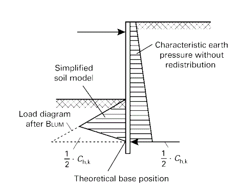
However, Blum’s method was known to be conservative. Another correction to this is shown in the image below, where the concentrated force to be accounted for by the extra depth is halved and this is what Prosheet does, though it ignores a 10% minimum recommended in the source of the image. So the extra depth needed is more in the order of 10% (and actually 6% in the example I posted above). Though not intended to be a margin of safety, Teng’s extra 20% would therefore give FOS of 1.2~1.3 assuming the soil parameters were dead on. A little conservatism in the parameters and the typical 1.5 FOS will be met, but that conservatism needs to be there if 1.2~1.3 FOS isn’t enough.

BlumHalved_irvhjo.gif
 
Ron - why should we all do whatever PEinc says? There are a few different ways to design flexible walls and not all of them are "right" - whatever that means.

As long as the engineer understands what they are doing that's the key.


Although I don't disagree with you on your point TheRick, the reason I said what I said, and Ron echoed it, is because on earth retention structures PEInc is the local expert.

And for someone unfamiliar with them, having PEInc provide some guidance on the matter is the best thing that could happen. If you'll notice he gave a knowledgeable and yet simple answer. Exactly what someone new benefits the most from.
 
TheTick109 is correct. That are many ways to design walls. They all work sometimes; they all don't work sometimes. However, in my opinion, walls that do not perform generally have problems from poor construction (mostly) or from changed soil conditions (less commonly). A wall will not fall over or slide because you used too many multipliers on the embedment. So, use as many multipliers as you feel comfortable using. I prefer to follow what Teng clearly SAYS in his simplified method and no more, except for maybe rounding a beam length up to the next commercially available 2.5' length (e.g., 17.5', 20', 22.5', 25', 27.5', etc.). This has worked for me for almost 50 years and thousands of walls without a single problem. For years, I successfully used even another, unpublished method for designing cantilevered, non-gravity walls that gives even shorter, lighter beams - as long as the soil is not a soft, unsuitable soil. If you have soft, unsuitable soils, you probably should not be designing a cantilevered wall. Ultimately, the design method you use may have to be the one that project specifications or agency design manuals require.

 
PEinc, why do you think Teng gives a range of wall embedment lengths for the conventional method (for FOS 1.5~2.0) but a single length for the simplified method that is shorter than the short end of that range?
 
Not sure, steveh49. Did you ever design the same wall by both methods as a comparison? I have. I also attached a comparison of Teng's conventional method for the USS Sheet Pile Design Manual, Example No. 1 vs. Teng's simplified method using CivilTech Shoring Suite. In CivilTech, I used the same soil properties as did USS's Example No. 1. In CivilTech, I used an active pressure multiplier and adjusted the wall friction to give CivilTech's analysis the same Ka and Kp as the USS example. Otherwise, the comparison would not be as accurate.

EDIT: IMHO, the conventional method becomes a lot more complicated than the simplified method when you add in surcharge loads, especially Boussinesq surcharge loads.

Review of the results from two design methods shows almost the exact same bending moments and SSP embedments (prior to adding, only once, 20% more embedment for a safety factor). Result of the comparison? It should not matter which method is used, but the simplified method is much easier, especially if you keep the driving pressures and the resisting pressures on opposite sides of the wall. Let's not over-exaggerate the undefined and unexplained "small error" between the two methods.

www.PeirceEngineering.com
 
 https://files.engineering.com/getfile.aspx?folder=c7bb4899-3578-439c-9c8e-9622d93c697c&file=14.0'_Conv._vs._Simpl.pdf
Review of the results from two design methods shows almost the exact same bending moments and SSP embedments (prior to adding, only once, 20% more embedment for a safety factor)

The final embedment of 11.83' vs 12.6' does appear to be a small difference (0.77' or 9") but that will depend on subjective tolerance. The 20% difference between depth for FOS=1.0 and the depth including FOS is 1.97' (0.6m) which makes 0.77' look more significant. What FOS are we actually getting? Using the factor on Kp mentioned by TheRick109 (aka Teng's more desirable method), your 11.83' gives FOS=1.37 vs 12.6' conventional method FOS=1.52.

That's without accounting for the small error in the simplified method. Try my post from 4 Dec 10:53 as an order of magnitude. The correction is 130mm (5"). Again looks small on its own, but now 9" + 5" = 14" out of approx 24" providing the FOS is in doubt. Nominal FOS would be a shade under 1.3 now for the shorter embedment when presumably we were expecting 1.5 based on Teng.

I also want to clarify something about the attachment in your last post. Are the handwritten comments and the comments in red printing yours? On page 3, there's a note to use 28' when the calculated length was 25.83'. On page 9, US Steel proposed 27.5' and there's a note "Remember, US Steel sells steel!"
 
steveh49 & PEinc - I think some information may have been lost in translation over the years when developing design manuals.

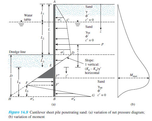
From my engineering textbook by Das:

Capture_1_mjve6v.png

Capture2_s0vggk.png


It appears that some folks may be "double dipping" as PEinc suggests, using a factor of safety on the passive coefficient AND increasing the embedment.

I will note that this is for the pressure distribution shown only.

The other pressure diagram I showed above with active and passive pressures on one side of the wall explicitly calls out the need for "double dipping" but as we are discussing, it's primarily due to the differences in methods.

I've done walls both ways too just to see the differences as well. The designs never seem to deviate more than 1 to 2 feet difference in the overall pile lengths - this isn't a space shuttle LOL.

I do a lot of construction engineering where contractor's typically tell me their equipment weighs 200,000 pounds plus or minus 100,000 pounds so I don't mind a little more conservatism sometimes.
 
I gave detailed designs using both methods. Considering the accuracy of the soil properties, the 2 methods gave practically the same results. Both methods work. Why is more discussion needed?[deadhorse]
The RED notations are mine. I made them when teaching a university course in Foundation Engineering.

 
Just taking the opportunity to discuss something with the subject matter expert. Were the handwritten notes by an employee you got to do the calcs?
 
TheRick109, there are big differences in design results when you put the safety factor on Kp. Doing so will give heavier, longer sheets and soldier beams with greater and unrealistic deflections. Just like LRFD should not be used to calcurate deflection, neither should Kp be divided by a safety factor when checking deflection.

 
steveh49, the conventional design calcs were photo-copied from the USS Sheet Pile Design Manual. I added the red notes. I did the CivilTech calculations myself.

Do you use a computer program to design cantilevered, non-gravity walls? If so, which program and which method does the program use?

 
steveh49 - I see the biggest differences when switching between Coulomb and Rankine for lateral pressure coefficients. It has been noted in many texts that a ratio of delta/phi greater than 0.33 is unconservative for the passive coefficient. There are even follow up studies to Coulomb's theory noting this and suggesting the use of "correction factors". This is why some state DOTs do not allow the use of Coulomb, and also mandate a certain method is used so that these "debates" do not occur for flexible walls. As PEinc stated above, several methods work so I'm done discussing.
 
@TheRick109: Can you post the equations 14.1 to 14.20?

Rather than think climate change and the corona virus as science, think of it as the wrath of God. Feel any better?

-Dik
 
PEinc,
TheRick109 reminded me that I have recently used Prosheet and that's what I used for the FoS calculations (9 Dec 13:17). I don't design these walls much in my current job but checked some temporary walls earlier this year with Prosheet and still had it installed. I have used Wallap in the past and also spreadsheet/hand calcs.

Prosheet uses the simplified method and matched Civiltech to a few millimetres. It has an "included overlength" in its output which is the correction I posted on 4 Dec 10:53, though I ignored that when using Prosheet for the temp walls as it is not explained in the manual. I figured it out in the course of this discussion.

I agree that deflections and bending moment will be larger if using 1.5 FoS on Kp. That would probably be similar to an ultimate limit state design so used to check stability and strength against those limit states rather than allowable limits.

I'm still puzzled by the handwritten comment on your Civiltech calculation to use 28' in the context of this discussion and the comment on the US Steel calculations.
 
Status
Not open for further replies.

Part and Inventory Search

Sponsor