Continue to Site

Eng-Tips is the largest engineering community on the Internet

Intelligent Work Forums for Engineering Professionals

  • Congratulations KootK on being selected by the Eng-Tips community for having the most helpful posts in the forums last week. Way to Go!

Cantilevered Concrete Slab Supporting Load Bearing Wall

Status
Not open for further replies.

spieng89

Structural
Jun 30, 2015
172
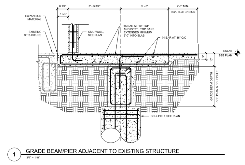
I have a situation where due to existing structure I need to install bell piers a few feet away from a new load bearing CMU wall. I plan to design a cantilevered structural slab to pick up the load bearing wall and continue the structural slab back past the grade beam until the slab on grade/structural slab interface can withstand the resultant shear. I wanted to confirm my checks were adequate:

1. checking shear/moment strength of cantilever structural slab at grade beam
2. checking deflection at load bearing wall and back span deflection beyond the grade beam
3. checking shear at structural slab/slab-on-grade interface

Any other concerns I should look out for? See preliminary detail below:
Capture_hakjmr.png
 
Replies continue below

Recommended for you

Make sure the primary span (at the other side of the cantilever) has enough dead load to resist the load of the wall. I don't think your 3' length of thickened slab will cut it. I would extend that at least 10' prior to transitioning to the thinner slab on grade, based on gut feel alone. You obviously need to do the math.

Also, the foundation piers will see much more load from this condition than a simple tributary area condition.
 
But the downward stress (moment really) from the load-bearing wall on the left side of the vertical is an upward moment at the 5 inch thick slab as well. Is that not now the point of failure, since a 10 inch slab required to resist moment across the vertical?
 
I'll chime in with the answer to the question you didn't ask: I think you should consider using a grade beam parallel to the existing bldg. to carry the wall, using another grade beam to cantilever over the pier in the perpendicular direction, and allowing the slab to rest entirely on grade.

To me, this makes the system more rational and doesn't dictate the sequence of construction. The slab can then be placed after the roof is on and have control joints, etc. that are more typical slabs.

Maybe there's a reason you already ruled this out, but that's my first thought when I see your section.
 
kipfoot, I actually was just discussing that scenario with my supervisor and it seems to make to most sense as well. Trying to balance the load is making the back span of structural slab too long in that it's beginning to interfere with other structural elements that can't be moved. I also didn't think about sequencing yet, good point.
 
Cantilevered beams are probably the best solution but another possibility is to use a grade beam under the bearing wall supported by offset piles placed as close to the existing building as possible.

BA
 
I agree with Kipfoot, keep the load to piles defined and rational. I would only ever do the cantilevered slab if pouring a beam meant undermining the adjacent structure.
 
Both atrizzy and kipfoot have given good advice. If you use the grade beams as kipfoot suggested, you will need another line of piers to resist the uplift on the cantilevered grade beams.
 
Hokie makes a good point, ideally though you'd have a set of piers at a reasonable distance back anyway.
 
Here's what I would do:

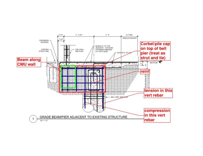
Just place an offset pile cap on the pier and resolve the forces in tension and compression in the rebar.
Run a grade beam between these at the CL of the CMU wall above.
Your slab on grade is now just a typical slab on grade.

All this depends on how reasonable your loads are and if you can resolve the moment into that pier via tension and compression in the rebar.

Document1_jthzzu.jpg
 
I agree that offset piles can be a good solution but the eccentricity of load puts a tensile force on the slab or a compressive force on the existing foundation or both. The most economical solution depends on the plan layout of the new structure and the magnitude of load on the bearing wall.

BA
 
If the piles are drilled piers on the scale of what OP's shown, the eccentricity may also be able to be resisted as bending moments in the pile and a resisting soil force couple/set. I see that a arrangement a fair bit on institutional buildings with steel columns coming down on the piles, inboard of the wall system.

Any chance that block wall is a fire wall that needs to remain standing if the new building burns down?

I like to debate structural engineering theory -- a lot. If I challenge you on something, know that I'm doing so because I respect your opinion enough to either change it or adopt it.
 
DETstru said:
Just place an offset pile cap on the pier and resolve the forces in tension and compression in the rebar

This would be the most ideal and what I tried initially after posting here. The deep beam design is no problem, but I'm not sure I know a valid way to design a bell pier for moment at grade. Is it as simple as getting lateral resistance values from the geotech and turning the moment into couple forces?

KootK said:
Any chance that block wall is a fire wall that needs to remain standing if the new building burns down?

At the moment, the designers are trying to determine if this should be a fire wall or just fireproof the corridor bay adjacent to this wall. Any particulars I need to look out for if this is a fire wall?

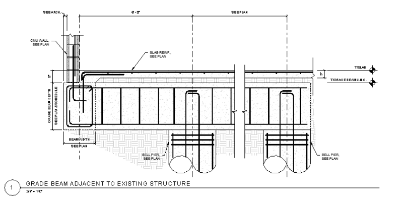
I've revised the detail to the below as it provides the simplest construction so far:

Capture_pbqolq.png
 
I can't tell from the scale of the sketches if you've already considered this, but I'd determine the grade beam depth and top of pier elevations such that the excavation does not undermine the existing grade beams. i.e. bottom of grade beam under the wall = match existing.

It complicates the rebar detailing a bit, but the bottom of the cantilevered portion of the beam shown in section could slope up toward the existing wall, if necessary.
 
OP said:
Is it as simple as getting lateral resistance values from the geotech and turning the moment into couple forces?

That's about how I do it. As BA suggested, it may be attractive to utilize your slab in tension for part of that couple. Unless you isolate things, that's probably where the tension will want to go anyhow.

OP said:
Any particulars I need to look out for if this is a fire wall?

This situation has caused me all kinds of grief when the wall needs to be able to free-stand after the new building collapses.

- high flexural demand on the wall acting as a cantilever. Often need a thicker wall or intermittent piers with horizontally spanning wall.

- the cantilevered block walls tax the grade beams pretty hard in torsion and everything else down the line in other respects. Particularly so if you're being conscientious and actually trying to calc out the rebar detailing in the joints properly (as opposed to just developing bars). In this one respect, your original solution may have some advantage. Relatively easy to dump the wall moment in slab uniformly. Easy... just not cheap. One could employ a hybrid solution where you use the grade beams for gravity but the slab for moment.

- In addition to resisting modest wind load as a cantilever wall, sometimes you need to design for a "pull down" breakaway load acting the wall as the adjacent framing pulls away per NFPA. Makes a tough thing even tougher.

I like to debate structural engineering theory -- a lot. If I challenge you on something, know that I'm doing so because I respect your opinion enough to either change it or adopt it.
 
Kootk, all good points. To go a bit off topic though...Main issue I saw with that is designing the "melt away" or slip connection for the steel joist at top of wall to provide a valid separation between wall and structure. Contacted Vulcraft, but they had no connections that were approved. Poked around the internet, but nothing viable as of yet. Difficult part is designing that connection for both diaphragm and uplift forces, but hopefully it doesn't go down that path.
 
Another trick is that, in my opinion at least, it's wholly irrational to expect the fire to be located right below the thing that you're counting on melting away. Realistically, it's far more likely that the fire will be melting your framing a bay or two over and when that comes down, it'll be tugging on the wall, with the melt away connection completely in tact.

I like to debate structural engineering theory -- a lot. If I challenge you on something, know that I'm doing so because I respect your opinion enough to either change it or adopt it.
 
For steel joist to fire wall connections we've typically provided a bearing angle where the joists are welded only to the outer toe. Then when the structure tries to fall away it hinges at the weld and breaks away. Luckily so far we haven't had to see if the detail works as designed.
 
Clever but, again, that only works if it's the joists supported on the angle that melt and fail. If it's the bay over, it's useless.

I like to debate structural engineering theory -- a lot. If I challenge you on something, know that I'm doing so because I respect your opinion enough to either change it or adopt it.
 
The best detail for a firewall is a double wall where each wall is firmly tied each side. It's like two separate buildings.

If a single wall is used, as it usually is, the best detail in my opinion, is to tie it securely from both sides and ensure that the structure on each side is capable of resisting the horizontal force on the opposite side if it should collapse in a fire. I agree with KootK that the fusible link or "melt away" connection cannot be counted on for reasons he stated.

BA
 
Status
Not open for further replies.

Part and Inventory Search

Sponsor