Continue to Site

Eng-Tips is the largest engineering community on the Internet

Intelligent Work Forums for Engineering Professionals

  • Congratulations KootK on being selected by the Eng-Tips community for having the most helpful posts in the forums last week. Way to Go!

Capacitor Bank Tripping, Suggestions Needed

Status
Not open for further replies.

Buckeye46

Electrical
Jun 23, 2018
20
I was called out to investigate a b-phase cap bank trip,It is one of the original caps on our system that has just always been an issue. It is an externally fused, grounded cap with two SEL 487V's using bus and mid-cap potential for voltage differential. I am being told the mid-cap ccvts have been tested many, many times as well as the cans themselves. There is no visible issues that we can find with it and at this point just looking for some suggestions. Maybe someone has ran into something similar.

The top waveform is the B-phase bus potential and the bottom waveform the B-phase mid cap potential at different times prior to it tripping. I aligned them for visual purposes. The mid-cap potential is steadily decreasing, leading to a positive differential. I sat there and watched it slowly creep up until it tripped. It isn't a very violent increase just slow and steady. The cap in question is cap 2, protected by C201 as seen below.

Trip threshold is 0.57 V/sec.
Bus CCVT ratio 4348 - 500kV/115V
Mid-Cap CCVT ratio 2000 - 230kV/115V
KBV Correction Factor - 1.0307 (Existing, commissioned K Set Value)

Just to clarify this is a comtrade file. It does seem like there may be some 4th harmonic involvement here.
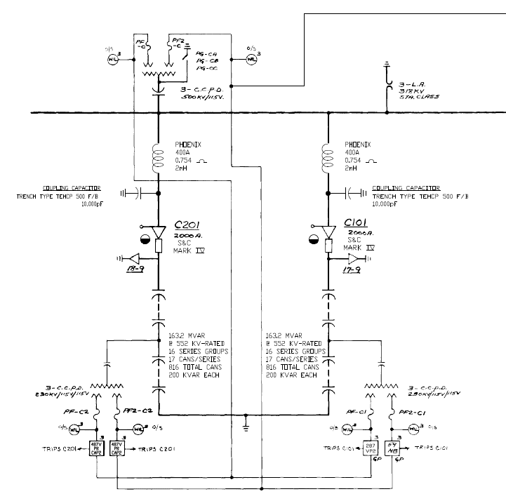
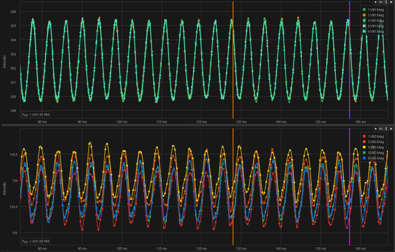
image001_xubtau.png


Cap_Bank_Potential_qrbpcb.png
 
Replies continue below

Recommended for you

Increasing capantence is a sign of failing dielectric. But I would not expect it to happen so fast that one could watch it.
Then again, it could be an internal MOV that is failing. And as it gets hotter it is reducing the clamping voltage.

The fuse may not be blowing as the 487V is operating so fast.

Look at replacing some cap cans.
 
Can you post the event file itself rather than just a picture?
 
How exactly does that work with CIP sensitive relays given it details locations and settings. I did that before and got a few messages stating that it wasn't a smart idea from other forum members haha
 
I found I could edit a .cev file with a text editor to remove the settings. Analytic Assistant had no trouble opening the modified file.
 
Well that's cool, it worked for the CEV's but It wouldn't work for the comtrade files where I do think things get more interesting. Unfortunately, my technician only sent me the comtrade files from todays test energization i should be able to get the cev's tomorrow. Since we sat there and triggered events constantly you would get to see the voltage degradation occur. The CEV's I do have are from the initial trip that occurred a few days ago. Events are below.

 
In deed, how does CIP work when you are almost required to share your settings with your next door utilities.

I had to explain this to our NERC people.

The settings are not classified, but the access to the relay is.
The other issue is giving information to the general public, but then again most would not have any idea what to do with it.

Just remove the location, and company name. We also don't need the passwords, and other access information.
 
From the CEV files time stamped 10 seconds apart, it looks the delta-B voltage changed by 0.07 from 0.58 to 0.65 whereas the other two delta voltages changed less that 0.02. Is this the same sort of change the trends in the first post are showing?

We have had similar increases in differential voltage on a similarly protected capacitor bank. Testing of our capacitor cans and PTs similarly showed no blown fuses. Hope you figure out the cause and can share it. As mitigation, our relay techs reset the k factor after visually inspecting the capacitor cans for blown fuses. I think they might end up doing the k-factor reset every one to three years.

Perhaps unrelated, is it normal in your area for A phase to be 2 percent lower than B and C phases? This magnitude difference is much larger that for my region(Washington state-USA). Typically in my area, B phase is always high by about 0.75%. I am a little puzzled that on the midpoint PT, A phase is instead high by 1.3 percent. Capacitor cans have a pretty wide manufacturing tolerance, so perhaps the change from 2 percent low to 1.3 percent high is just do to differences in manufacturing of cans.
 
When we test energized it, I saw it rise from 0.2 to 0.6+ differential in a matter of twenty seconds. I do think manufacturing tolerances and aging can have a decent impact. Especially on something like this that is from the 80s. I really hate performing K sets to mask issues. That has definitely been done on these caps as they have these phantom trips then you will re-ernergize it and everythings fine. That's one of the reasons the old DPU and 287 relays were swapped for dual 487V's. We tried telling people it isnt going to fix the problem because the relays were testing fine. Typically in a 500kV yard like this one its less common to have phase imbalances. Most of the imbalance can be chalked up to the manufacturing tolerances and aging like i mentioned and the k set should compensate for that. It is possible there are failed cans that just havent blown the fuse yet but i dont see that explaining the mid cap pt voltage decreasing constantly until it trips. I would expect can issues to cause the voltage to be low/high but to be steady at that point not keep going down so quickly.
 
Are there energized overhead lines in the vicinity of the cap banks? Particularly overhead lines that are place very asymmetrically relative to the cap banks. I've seen perfectly good cap banks that can't stay in service simply because voltages coupled from overhead lines continuously change the voltage balance in the caps.
 
There is not any overhead lines, this is one of our largest 500kV subs from space perspective and the caps are in a corner all alone. The cans all tested good as of today so now I guess we have to start getting more creative to find the issue.
 
That sounds like a nightmare to test. If the trouble phase is in the shade, you could get some oddities as things warm up. Looking at the records, the trip settings make it look like the tap point is between groups 8 and 9 (87TP1P and 87TP2P are identical). If this is true, the CCPD's are being stressed pretty hard - 114% with 303kV on the 500kV side? The K factor should be less than 1, too, around .9. Voltages and K factors look like the match up better with a tap between groups 7 and 8. You may want to raise the trip point to operate for 3 failed elements instead of 2, and see if things stabilize. It sounds like not even one is showing failed when it trips. If the tap point is between 7 and 8 the settings may need tweaked anyhow.
 
Status
Not open for further replies.

Part and Inventory Search

Sponsor