Continue to Site

Eng-Tips is the largest engineering community on the Internet

Intelligent Work Forums for Engineering Professionals

  • Congratulations SSS148 on being selected by the Eng-Tips community for having the most helpful posts in the forums last week. Way to Go!

Capacity of Steel Girder Truss when you know the Tension and Compression Loads

Status
Not open for further replies.

Tyannotti

Structural
Apr 20, 2020
2
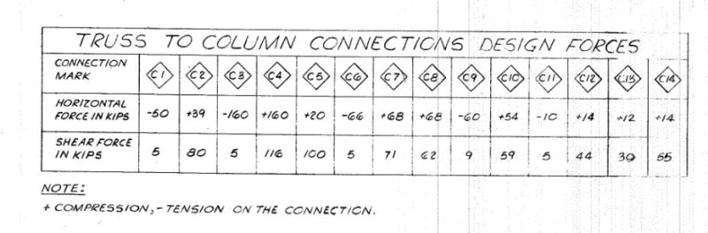
Does anyone out there know how to use just the tension and compression loads to find the total capacity of the girder in PLF? Or to convert to equal point loads?

See the attached sketch.

According to the attached drawing the reaction is 99 kip - correct? So, that would work out to 2,148 PLF capacity (99,000 lbsF x 2/92'-2") - correct?

But I want to get the capacity (or point loads) by using and verifying the tension and compression forces (when given).

In other words, if all I had was the tension and compression forces - what would the capacity be in PLF?
 
 https://files.engineering.com/getfile.aspx?folder=dcf54503-eeff-4c65-806b-874f362af2f2&file=Capacity-PLF.pdf
Replies continue below

Recommended for you

Method of joints.

With all of the member forces and the truss geometry provides you with all the info to find all of the “P’s”.

gjc
 
Tyannotti,

If you know you are dealing with a uniform load, you have the reaction in the end vertical, in this case 99k, so with a span of 93', the uniform load would be 99*2/93 = 2.13k/' or 2130 plf. But you already knew that. Incidentally, the panel point load at the left should be P/2, not P.

The top chord has a compression of 210k at midspan. It rises 1' in 93/2 or a slope of 0.02151. But your dimensions are probably out to out (I don't know what P/P means), so the depth the engineer would use is the distance of the normal between centroid of top chord and centroid of bottom chord. The chords are 8x6x1/2 angles (LLV?), so the vertical distance between centroids of chords is 12'-6" less 5" = 12'-1". The normal distance is 12.083 cos(slope angle) = 12.08', say 12' even.

Midspan moment, M = WL/8 = 210*12 = 2520'k. So W = 2520*8/93 =216.8k and w = 2.33k/' or 2330#/', which is about 9% more than found before. The reaction would be W/2 = 108k, again about 9% more than 99k. Probably the reaction is more accurate but I don't really know.

mtu1972 suggested using the method of joints. That may not be accurate for the point loads in the middle few panels of the truss because forces in web members are greater for unbalanced snow load; the listed values would not reflect the true value for a uniform load across the entire span. You also must know whether the engineer is specifying service loads or factored loads, usually the latter.

I'm not sure why anyone would perform the calculations above and hope you will explain why you need to do them. Normally, design loads are given in the general notes, so it would be much easier to determine the load on a truss by simply multiplying the given unit loads by the tributary width.

BA
 
If there were just one load case and you knew for sure that the reported chord forces were exact, the capacity in PLF can be easily found by either method given above.

If the truss forces provided are some kind of enveloped solution representing various non-equal point load combinations, the point load on each panel would be difficult to ascertain. This is not as likely in a plain roof truss as it is when there are significant hanging loads to consider.

And don't forget you have 15% or so which is self-weight which gets deducted from your allowable load 'P".
 
I agree with JLNJ on all of his points. If a truss is designed for several load cases, the drawings should indicate maximum load for each member to enable the fabricator to design his connections. That means the forces shown on the drawing are not necessarily for a particular load combination which suggests that the notion of determining panel point loads from member forces is questionable.

BA
 
My earlier response was just meant to find each “P”. I was not assuming they would all be equal.

I agree with the other comments regarding DL’s, etc.

Based on the hand-drafted drawing, I assumed this building was quite old. Before computers and CAD we mostly only worked out the worst load case. Where I worked, we did not list member forces as shown, but drew a Maxwell diagram so the steel detailer had the member forces to design the connections.

gjc
 
Beautiful drawing.

Aren't those diamond call outs the horizontal and vertical end reaction components? If not, you might use the vertical component of the terminal webs to estimate the reactions as mentioned previously.

It appears to me that these trusses are continuous rather than simple span. That will complicate an evaluation of capacity as a function chord forces.

c01_pmaz29.jpg
 
I suspect that we could be of more help if you gave us a look at the framing plan.
 
There are nine different trusses.

In the case of T1, the left end diagonal rises approximately 9'-4" in a length of 5'-2.5", so the angle is 60.6 degrees. The shear is 92*sin(60.6) = 80 kips. For the right end, I found the shear at the bottom chord to be 117 kips. This compares with 80 and 116 kips for connection C2 and C4 respectively. The top chord has 5 kips at each end, so the total load on the half truss is 80+116+10 = 206 kips.

It is not a uniform load. The first node left of the interior column has diagonal forces of +43 and -143 left and right of the node, a difference of 100 kips. This suggests that a concentrated load of about 80 kips occurs at that panel point.

Truss T2 appears to be a cantilevered truss with a downward reaction at the right end and a downward reaction of 76 kips at the column. Not sure why the horizontal force is different at C6 and C7 (66 and 68 kips respectively) but the maximum moment for T2 is approximately 67*8.8 = 590'k.

This is not a satisfactory method of determining the strength of the trusses. As KootK suggested, the framing plan would be much more help. But you knew that already, didn't you Tyannotti?

BA
 
Status
Not open for further replies.

Part and Inventory Search

Sponsor