Continue to Site

Eng-Tips is the largest engineering community on the Internet

Intelligent Work Forums for Engineering Professionals

  • Congratulations KootK on being selected by the Eng-Tips community for having the most helpful posts in the forums last week. Way to Go!

Capstan/Pulley Radial Load calcs

Status
Not open for further replies.

Kishore1234

Mechanical
Oct 8, 2015
9
Hi all
I have been trying to calculate radial loads on a capstan for a belt drive system. I have not been able to find much on this topic; or the ones I have found seem too complex as these methods uses Fourier series making things too complicated.

I found a research paper for this which has a simple equation to calculate the pressure acting radially upon the capstan/pulley.
pressure P(Θ) = T(Θ)/(R.b)
where T(Θ) is the Tension dependent upon Θ
and R is radius of capstan; b is width

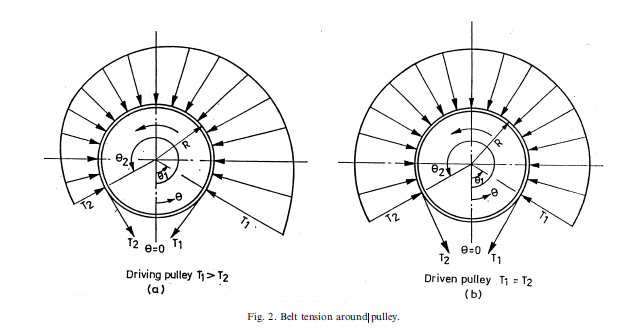
As it is a driving pulley, the belt tension is different on either side. The tension profile can be seen below (image).
Tension_Profile_tzknpo.png


Based on the formula and after calculating the radial pressure load; I've found the radial pressure load profile to be the same as the belt tension profile; i.e. the load increases as you go along the circumference (where belt is wrapped) towards the high tension side. Hence the pressure peaks out on this side.

As this is a dynamics case, I didn't think using a static basic pulley force resolving would give accurate results. But I am not sure if this technique is correct or even close.
Can anyone please provide me guidance on this? Any help would be appreciated.

Regards
Kishore
Stress Engineer
 
Replies continue below

Recommended for you

Hello Kishore,

at belt pulleys "in the field" during design not the full angle of contact is to be used to transmit the circumferential force. So, with an "angle of utilization" smaller than the angle of contact, the vector of the resulting load is different than what would be assumed as per fig. 2a.
In order to derive the distributed pressure loads onto the pulley body I'd propose that you don't skip calculation systems just for their complexity but seek out the applicable system as per your specific task and stick to it.
Weak points of the pulley mantle are welds around the circumference to attach end discs (look for input on T-shape design end discs) and discontinuities as e.g. a tiger named stiffener disc which to my knowledge up until now has not been ridden successfully.
There's been lots of pulleys gone for inadequate design, so pls. allow me to say that the other way round there's lots of experience to be learned from. i propose you seek out some sources on belt conveyor re belt pulley design for deeper insight.
Regards
r.
 
Hi RolMec

I have been trying to find good sources but been out of luck so far. The sources I found makes use of Fourier series leading to a complicated calculations which varies depending upon the source (so do the results). I have been unable to find a clear representation of the radial loads acting upon the pulley whether they were experimental or theoretical. They seem to be different on every source that I could find.

I got the links below if you would like to have a quick look. And they seem to support the methods (Euler method shown above) in a way. But I do understand that the belt contact is not as represented above, in reality. I was going to assume that in order to use a worst case scenario of the radial load profile; so that I could use it for my FE Analysis.

Source:
([highlight #F57900]Not sure if you will have access to this)[/highlight]

Link
Link
 
Isn't a capstan a bit different than a belt drive? A capstan uses controlled tension of the belt around the driving/braking pulley to modulate friction, and only requires a single pulley. A conventional belt drive requires at least two pulleys, and uses controlled tension on both spans of the belt to produce a consistent traction capability.
 
Hello Kishore,
the first link just shows the abstract, it was the second link that didn't work for me over here.
However..., I asked a bit around and got a lot of replies on the theme of "proprietary information". Some people however developed their own calc tools from the theories existing for the contact of a rope on a rope drum. It seems also that there's some type of FEA - modelling done considering wrapping with an elastic band & contact modelling of this. Verification of any theoretical approach by stress / deformation measurement is not unknown.
Early next week I shall try again asking around if there exists a paper explaining some basics, but then I'm running out of my depth.
Nevertheless, good luck!
Perhaps you try to connect some people in the business, there's reputable belt pulley mfgrs. around and perhaps you have a way to approach them?
 
tbuelna

That is true and I am aware of that.
But in this context, it is a belt drive system; whereas capstan is the drum (or pulley) is the housing on top.

I must admit I do not have extensive knowledge in this area.

Regards
K
 
Hi RolMec

Thanks for getting back to me again. I do appreciate the effort you are making. I have asked around, but without much luck though.
I have presented the above technique to our customers and so far they seem to be happy with it. But I wanted to be extra cautious so that we could minimise the risk.

Regards
K
 
Despite that I cannot directly assist you [in my experience, I have only selected a sheave from a supplier's established design].

I do however note that the distributions that you reference are "theoretical ideals", examples of practical distributions can be observed in Figure 11 of the following:


In Australia we have a standard for mining sheaves AS3785.7, though it apparently it does not directly address your enquiry either.

Perhaps you could just apply 2 x T1.

Regards,
Lyle
 
Hello Kishore,

the basic paper over here on this subject is a Phd thesis: H. Lange "Investigations on the loading of belt conveyor pulleys", University of Hannovre (Germany); 1963.
Yes, this is using the full analytical toolset of the Fourier series. There's several more thesises from the same university on similar subjects.
Some input I got indicates that abovementioned workarounds are what people do with FEA being the tool of choice for singular pulley designs / small numbers.
Finally, this discipline's bases are a lot of "experience gained" and even trials & testing, so pls. be careful when it comes to relying on simplifications and doing manufacturing design from purely analyical approaches.
Best of luck,
Regards
R.
 
There is a very simple relationship between the belt tension and the radial contact pressure at any given point on the pulley.
The greater the curvature the greater the contact pressure. In your case the curvature is constant. The actual tension at any point can be very complicated to calculate because it depends on friction and stretch in the belt. However, in your case you should know what T1 and T2 are because they both are controlled by you. Tensions at any other point must be between T1 and T2. Assume a linear or exponential curve. Does your answer need to be any closer than that?

Now, if you are trying to calculate bearing loads all you need to know are the T1 and T2 vectors.
 
Hi RolMec

I have been trying to find that paper for a while but without luck. Do you have access to the paper by any chance?
Thanks for your help anyway.

Compositepro

I think what you are trying to say is basically the same thing I posted above, from what I understand. I have used a linear relation of the belt tension in order to workout the pressure at different angle (along the cirum).
We've employed a bearing loading method as well, which was a pretty standard method for us in this type of situation. But the above mentioned method seems more realistic than bearing method.


Regards
K
 
Status
Not open for further replies.

Part and Inventory Search

Sponsor