Eng-Tips is the largest engineering community on the Internet

Intelligent Work Forums for Engineering Professionals

  • Congratulations waross on being selected by the Tek-Tips community for having the most helpful posts in the forums last week. Way to Go!

Carbon Fiber Reinforce Polymer (CFRP) to reinforce the top of a drilled pier

Status
Not open for further replies.

dauwerda

Structural
Sep 2, 2015
1,027
0
36
US
I had an interesting call today and I am looking for some help and opinions.

Background:
This is in regard to the construction of a substation, so lots of cantilever columns with 4+ anchor rods. These structures are installed without any grout under the baseplate, instead they are installed with the baseplate clamped between a lower leveling nut and the upper nut, with no more than two anchor diameters space between the top of concrete and the bottom of the base plate. The foundation reactions range from 2 kips of shear and about 10 kip-ft of moment to 50 kips of shear and 2500kip-ft of moment. Foundations are drilled piers that range from 2ft diameter (lower loads) to 8ft in diameter (higher loads).

Issue:
Apparently when the contractor installed the rebar cages for the drilled piers they were allowed to drop to the bottom of the drilled piers, so where the first hoop should only be 2" below the top of the concrete it is instead anywhere from 1ft to ??? below the top of the concrete (they have started scanning as well as drilling holes to locate the rebar for each pier). They are now looking for a way to remedy this issue.

My thoughts:
Most if not all of the anchors are pretty long (minimum of 25x anchor diameter embed depth and more in most cases), I haven't run any numbers yet but I'm thinking tension capacity of the anchors will be less of an issue (still plenty of lap with the vertical rebar) and the shear will be more of an issue. So, the first thing to do will be to check anchor capacities as if there is no reinforcing and if it checks out for some of the structures, probably no further action will need to be taken. For the structures/anchors that don't check out, my first thought was to reinforce the top of the piers with CFRP. The problem is, I don't have any experience with that.

What do you guys think? Is CFRP a valid solution? What other ideas or solutions do you have? Has anyone ever run into this before?
If CFRP is a good solution, can anyone give me any pointers/background on how that is typically coordinated - is this a specialty design that the provider/installer performs or would they be looking to me for design info?

Thanks!
 
Replies continue below

Recommended for you

Rationally, I think that you start by asking yourself this question: if the CFRP wrap were outer hoops of rebar instead, would that work? In a lot of cases, I would argue that it would not. Imagine doing the Widianto paper checks but with no cross ties.

If you decide to explore CFRP further, you might engage someone like Quakewrap to help out. I once did delegated engineering for them on a marine pile that needed shear reinforcing and it was pretty neat. Of course, shear reinforcing is not anchorage reinforcing so the analog is imperfect.

 
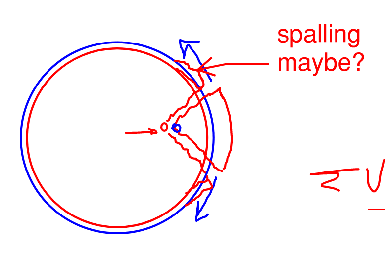
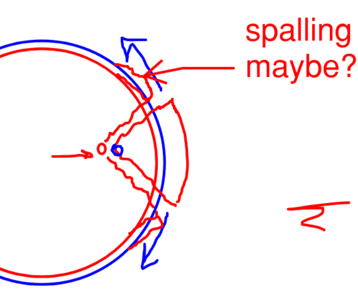
This is the picture that pops into my mind when I contemplate this. A large radius of curvature on the hoop reinforcement works against your here. Never mind the spalling business. Drifted into thinking rebar instead of wrap... That said, the CFRP equivalent of that would be the CFRP peeling off of the pier.

C01_vgqbqr.png
 
The benefit of CFRP wraps, and why it has been used for seismic strengthening of columns, is that it contains the concrete preventing spalling. CFRP has very high tensile strength which is what is needed to resist outward internal pressure. CFRP wraps may not help much with column bending. But definitely talk to a specialty firm who should do both the design and installation.
 
SWComposites said:
...is that it contains the concrete preventing spalling.

I agree with that in the confinement sense where:

1) you have outward pressure all around the pier

2) a uniform-ish hoop stress in the reinforcement

3) the spalling tendency is created by axial stress (usually bending)

I don't feel that logic is applicable to a situation like this, however, where the breakout is a localized thing caused by a transverse stress rather than a longitudinal one. You're handle suggests that you may be more adept at this kind of thing than I, however, so I'd welcome the opportunity to be re-educated.
 
Maybe the wrap works because of its extremely high modulus of elasticity. It just doesn't like to stretch and does a better job of confining than circular ties.
 
Not sure where your located, but Simpson Strong-Tie has good technical assistance.
I believe they will assist with the design and use a preferred installer that is experienced and competant to install FRP
 
JLNJ said:
It just doesn't like to stretch and does a better job of confining than circular ties.

1) I just don't see this as a confining exercise. More direct force transfer.

2) I'd think that the CFRP would have to be damn stiff to actually prevent a breakout crack pattern from forming prior to engaging the CFRP. And, once the breakout crack forms, you're back to the issue of the CFRP peeling off.
 
I have two ideas for alternate fixes but, frankly, I don't love either:

1) Drill dowels into the side of the pier to be the Widanto cross ties after a fashion. Based on your situation, however, I suspect that the dowels would have to be painfully long. they might also have to be anchored at the perimeter of the pier with curved anchor plates or something.

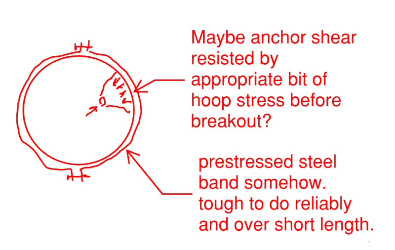
2) The wacky concept shown below which may suffer from all manner of practicality issues. The difference between this and the CFRP is that you're inducing the confinement action ahead of time rather than passively waiting for the load to induce them.

C01_gavdpy.png
 
Is ductility a concern in the connection? Even if you can get over KootK's issues, you'll have a brittle failure mechanism controlling your structure to foundation connection.
 
KootK, your idea might not be entirely wacky. A few months ago we were investigating a similar idea with some prestressing strand running through a dogbone and tensioned with a monostrand jack.

Our application was temporary, so you might have to encase the whole thing in concrete for durability. But a PT contractor should be able to manage it pretty easily.
 
@SWComposites: thanks for the info. That said, I feel that those articles support my position on this. The reinforcing applications described in those articles include direct shear, direct flexural tension, and axial confinement. None of those creates a peeling situation like dauwerda's shear anchorage breakout problem does.

Lo said:
A few months ago we were investigating a similar idea with some prestressing strand running through a dogbone and tensioned with a monostrand jack.

Neat. So kind like how concrete silos are sometimes post tensioned circumferentially?

As long as we're indulging creativity / insanity, another proposal:

1) Weld up a ring of steel larger than the pier. Maybe toss some studs on it for sport.

2) Add a strain gauge to the exterior side of the ring.

3) Place the ring over the pier concentrically.

4) Fill the annular void between the ring and the pier with a grout deliberately chosen to be expansive.

5) Let the grout expansion prestress the steel ring.

6) Check the strain gauge to verify the circumferential hoop stress.

Obviously, one would won't to do some basic creep / expansion calcs along the way to make sure this all isn't a horrendous waste of time.

Disclosure: I've never done this nor heard of anyone doing this. I've no idea whether or not reasonable grout expansion rates could induce meaningful hoop stress in this way. I'm just and ideas guy here... somebody else needs to execute.
 
Thanks for all the feedback and discussion!

KootK, it seams your stance is that the rebar hoop that is supposed to be there does not add any meaningful increase to the shear breakout of the anchor. Is that correct? If so I agree that the CFRP would not be beneficial.
My thought is that the hoops do add meaningful benefit, maybe not quite as directly as typical ties in the Widanto paper, but I do believe the confinement they offer does a better job than you seem to think. I of course don't have any evidence of this other than having never seen it fail in this way.

I have two different ways I have thought about it, The first being essentially what is in the Widanto paper, where there is a strut formed between the anchor and the vertical bars and maybe even more directly into the hoops (hence confinement, there are typically 3 hoops spaced at 3" O.C. called for) and the hoop is the tie which has the tension force flow around it - working similarly to developing a hooked bar around the corner (I believe you have championed that before, KootK, as it is recognized in some other codes but is not addressed in ACI). My other thought has been similar only I have the hoop acting more like shear friction reinforcement.

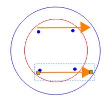
Maybe I am way off base with my thoughts above, but that is how I've always envisioned the mechanics working. One other thing to keep in mind is that your (KootK) images above depict an anchor with shear acting directly towards the edge, in reality, there are 4 anchors total, so the shear direction is really about 45 degrees to the edge (not sure if that changes anything).
Capture_t5zts9.jpg

In my head a CFRP wrap would work in the same way the steel hoops are supposed to work - maybe even performing better if they have a higher modulus of elasticity than steel.

Maybe it all comes down to how large the breakout crack might become before engaging the reinforcement (whether that be rebar hoops or CFRP), in my head the reinforcement would engage well before the crack became detrimental to the anchor (as long as the concrete is confined, it seems like concrete crushing would have to be engaged for the anchor to start moving appreciably). But, I also am not confident in any of this and that is why I came here looking for others opinions.

This type of foundation is used all over the country in substations and for highway masts/lighting and signs and I have seen many (well enough anyway) failures - none of which have been shear breakout of the anchors. As far as I know, there isn't actually any guidance on just how to calculate/use the hoop reinforcement for anchor shear reinforcement but I believe it is depended on in many designs.
 
This has been very informative, and I've learned alot about CFRP wraps. My question for the suppliers/installers of the wraps, assuming these shafts have the same typically rough exterior our drilled shafts do, is how rough of surfaces can they effectively be applied to?

Before spending any more effort on mitigation strategies, I would start with the calculating the shear capacity of the concrete, and see whether the any shear reinforcement is necessary. I wouldn't be surprised, given the moment/shear ratios, if the concrete was sufficient to prevent breakout, without reinforcement.

Even if the concrete isn't sufficient assuming an equal distribution of the the shear to the anchor bolts, I would look at whether an equal distribution of the shear force is a realistic or necessary assumption, or whether the anchor bolts on the 'backside', with the shear force pushing them towards the center can be assumed to take more of the shear.

I would guess the shear on the bolts isn't anywhere near their shear capacity. If that's the case, then you have to decide whether cracking of the concrete around 1 bolt, under the design loading which the foundation will probably never experience, constitutes "failure" of the foundation, if the other 3 bolts provide adequate shear resistance.

Rod Smith, P.E., The artist formerly known as HotRod10
 
BridgeSmith, the drilled piers usually have at least the top 2ft formed with sonotube, so at least the top portion should be smooth, you bring up a very good point about the part that would be cast against earth though.

I agree with everything else you are saying. I am actually not the foundation design on this or the one that has to make the final decisions. I am the steel structure and anchor designer (anchor design basically constitutes make it long enough the foundation designer has no issue developing supplementary reinforcement.), the foundation designer reached out to me both to keep me in the loop as well as look for ideas/suggestions to fix.

I am trying to turn it into as much of a learning experience that I can. The reliance on the back anchors only for shear was something we talked about on the phone this morning and in general I think it would be something I would be comfortable with.

What might then become an issue is that the front anchors are in compression (no grout), say they did break the concrete before shear was redistributed to back anchors, now you have an anchor in compression (near it's capacity), it is bent over at least some, and no longer has lateral support of the concrete to prevent buckling. Might be an issue, might not be.
 
dauwerda said:
KootK, it seams your stance is that the rebar hoop that is supposed to be there does not add any meaningful increase to the shear breakout of the anchor. Is that correct?

That is correct for a front loaded anchor which is the case that I've been speaking to. At best, you get that 15% capacity increase for the kind of reinforcement that runs perpendicular to the load and basically just increases the shear at which the breakout frustum would materialize. This is my understanding of what you've described here:

dauwerda said:
My other thought has been similar only I have the hoop acting more like shear friction reinforcement.

I wouldn't call that shear friction because it's plagued by edge distance problems. I get your drift though.

dauwerda said:
In my head a CFRP wrap would work in the same way the steel hoops are supposed to work - maybe even performing better if they have a higher modulus of elasticity than steel.

Sure, I agree that, whatever the steel hoops would have been doing, the CFRP hooks can likely do as well or better.

dauwerda said:
...I do believe the confinement they offer does a better job than you seem to think.

I'd like to stop using the term "confinement" in this discussion. It can be a vague term and I get why folks are using its here. The hoops, of any material, will help to confine (restrain) the shear breakout frustum from popping out to some degree. That said, when the CFRP guys are touting the miraculous confinement that their products produce, I 100% guarantee you that this is not what they are talking about. What they are talking about is the hoop stress developed when axial compression loads induce a Poisson effect in the concrete mass enclosed by the hoops. A tri-axial state of stress effectively, like in the lab in undergrad.

I feel that it muddies the water semantically to keep bringing up confinement here.
 
dauwerda said:
The first being essentially what is in the Widanto paper, where there is a strut formed between the anchor and the vertical bars and maybe even more directly into the hoops (hence confinement, there are typically 3 hoops spaced at 3" O.C. called for) and the hoop is the tie which has the tension force flow around it - working similarly to developing a hooked bar around the corner (I believe you have championed that before, KootK, as it is recognized in some other codes but is not addressed in ACI).

Whether handled via Widanto or handled via App D, I think all of that boils down to the model show below, taken from my previous sketch.

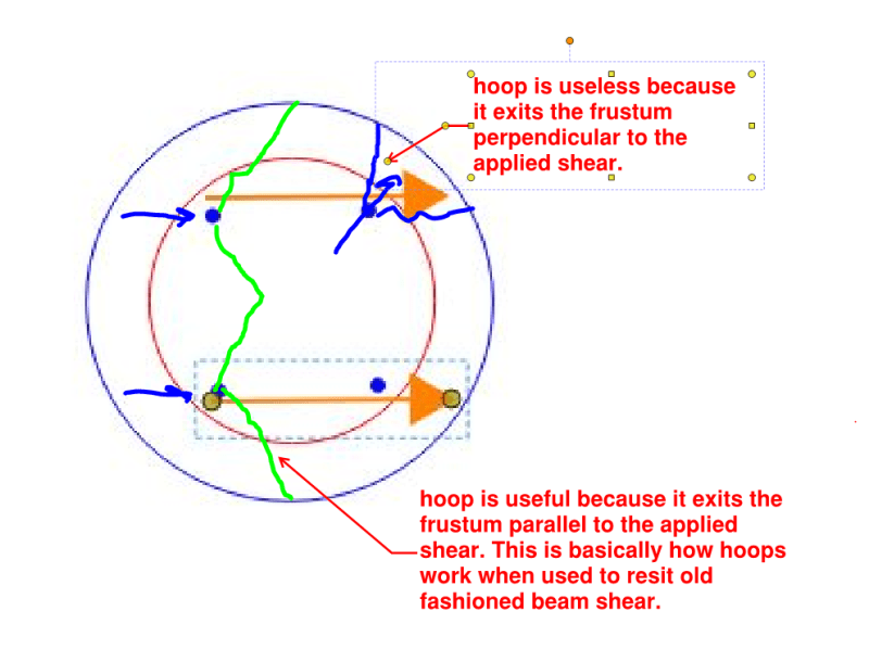
The issue du jour is the angle that the hoops make relative to the shear load when they exit the breakout frustum. If the hoops are relatively orthogonal the the shear load, then they'll be almost useless other than the 15% bump that I mentioned previously. If this angle is relatively parallel to the shear load, then the hoops become tension ties / supplemental reinforcing in the valuable sense. Because of this the angle of the applied shear load the assumptions made about whether the shear load goes to the front or the back are hugely influential. I'll elaborate in my next post.

c02_isuhfc.png
 
This is my elaboration on the influence of front loading vs back loading, based on the exit angle of the hoop from the failure frustum.

With regard to the front loading vs back loading, these are my thoughts on the matter:

1) Per ACI, if you're going to assume an equal distribution of load to the front and rear an anchors, that needs to be justified somehow. Weld washers, non-over sided holes, bolt clamping friction... something.

2) If you've got the justification for [#1], then I could support an equal distribution of load to the front and rear anchors. I could not support the justification of loading only the rear anchors unless we're assuming that the concrete failure frustum in front of the forward anchors is allowed to materialize which has been discussed. For that, my concerns would be:

a) As you mentioned, anchor rod buckling in compression over an effective length that is your standoff plus the depth of the shear frustum breakout, whatever that is.

b) Corrosion of the anchor rod if a vector for water intrusion has been created and the effectiveness of passivation has been compromised.

c) Because of your stand off, the anchors will be bent into an S-shape prior to the shear frustum breakout developing. Once the shear frustum breakout forms, the anchors will want to snap back to straight which will exacerbate any spalling tendency.

If the strategy for the CRFP here will be simply to keep the failure frustum from popping off of the pier wholesale, then perhaps a cheaper strategy would be to simply pour a new, reinforced concrete ring around the top of the pier. Maybe that causes problems with aesthetics or frost heave, I couldn't say.

c02_es5xap.png
 
dauwerda said:
...where there is a strut formed between the anchor and the vertical bars...

In truth, and even in the Widanto paper, I would say that there are not really struts being formed between the anchor and the vertical bars. I think that it's more accurate to view the vertical bars simply as distribution members that smooth out the delivery of load from weaker concrete struts to stronger steel bars at the connection points. Much like "padstones" in the UK parlance but operating in reverse.

With the GFRP wrap scheme, you really have no need of the vertical bars as distribution elements because the wrap will be vertically continuous rather than discretized as rebar hoops would be. So I would say that the GFRP solution would be agnostic to the presence of the vertical bars.
 
Status
Not open for further replies.
Back
Top