Hello everyone, I am working in an Spinning Mill of natural fibers. As a project in this mill I have to improve the control of the carding machine.
A carding machine is the hearth of the spinning plant, it parallelize the fibers each other in order to form a nap or a sliver. This machine consist of a series of rollers depending the use-end of a yarn, this machine influence deeply in the quality of a sliver and after in the quality of a yarn. We have an old carding machine, it is quite big with of cops one more that a normal one, that brings us a good quality sliver.
In order to improve the quality of the carded fiber and the control of the machine, my mission is to develop a control of each roller or the most important called workers and strippers that sum in total 24 rollers. When I talk about a control is to know the velocity of the rollers during the running of the machine.
In simple words I am looking a sensor that could be able to installed near the roller, at a side of them and then see the velocity of the roller in a display screen. As a metaphor, it is like installing 24 tachometers in each roller and see them a display.
I have asked some type of sensor in some of our local electric/electronics suppliers and they do not have any answer. Regarding the display an the interface for the data is not a problem we have seen even arduino projects with something like data.
The problem lays to find a suitable sensor (tachometer sensor, or something like that) that could measure constantly the velocity of the roller during the running phase.
I hope somebody could helps or guide us. Maybe someone that had a similar problem.
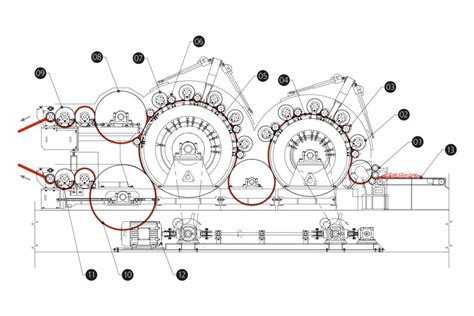
I post a schematic photo of a carding machine.

Workers and stripper rollers are the ones up, on the the big cylinders.
Thank you for your support
Best regards,
Tiamat
A carding machine is the hearth of the spinning plant, it parallelize the fibers each other in order to form a nap or a sliver. This machine consist of a series of rollers depending the use-end of a yarn, this machine influence deeply in the quality of a sliver and after in the quality of a yarn. We have an old carding machine, it is quite big with of cops one more that a normal one, that brings us a good quality sliver.
In order to improve the quality of the carded fiber and the control of the machine, my mission is to develop a control of each roller or the most important called workers and strippers that sum in total 24 rollers. When I talk about a control is to know the velocity of the rollers during the running of the machine.
In simple words I am looking a sensor that could be able to installed near the roller, at a side of them and then see the velocity of the roller in a display screen. As a metaphor, it is like installing 24 tachometers in each roller and see them a display.
I have asked some type of sensor in some of our local electric/electronics suppliers and they do not have any answer. Regarding the display an the interface for the data is not a problem we have seen even arduino projects with something like data.
The problem lays to find a suitable sensor (tachometer sensor, or something like that) that could measure constantly the velocity of the roller during the running phase.
I hope somebody could helps or guide us. Maybe someone that had a similar problem.
I post a schematic photo of a carding machine.

Workers and stripper rollers are the ones up, on the the big cylinders.
Thank you for your support
Best regards,
Tiamat
